High-speed paper-transferring device

A high-speed, paper-pressing technology, which is applied in the field of high-speed paper transfer device, hot stamping machine or die-cutting machine, can solve the problems of high-speed equipment, high impact force and fast wear of the paper transfer device, and achieve optimization The effect of high motion and paper delivery speed

Inactive Publication Date: 2012-04-11
HEBEI YUTIAN XINGYE PRINTING MACHINERY
View PDF6 Cites 7 Cited by
  • Summary
  • Abstract
  • Description
  • Claims
  • Application Information

AI Technical Summary

Problems solved by technology

The mechanical paper transfer device has many defects such as large impact force, fast wear, and various action relationships that cannot be modified at any time, and each functional part cannot achieve optimal action, and various disadvantages are prone to occur during the high-speed paper separation and paper transfer process. Meet the requirements of high-speed equipment

Method used


Image

  • High-speed paper-transferring device
  • High-speed paper-transferring device
  • High-speed paper-transferring device

Examples


Embodiment Construction

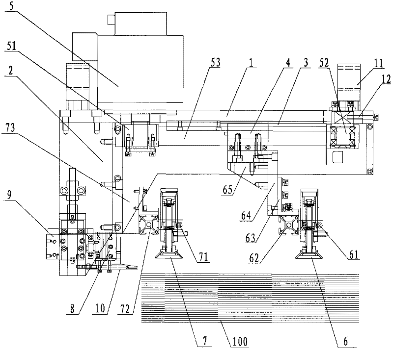
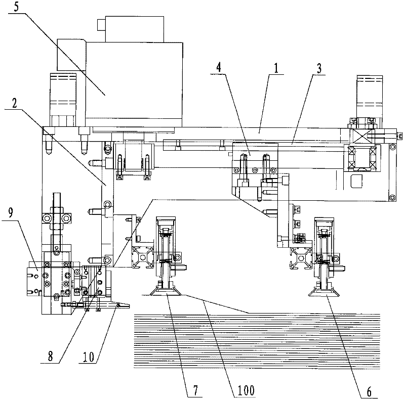
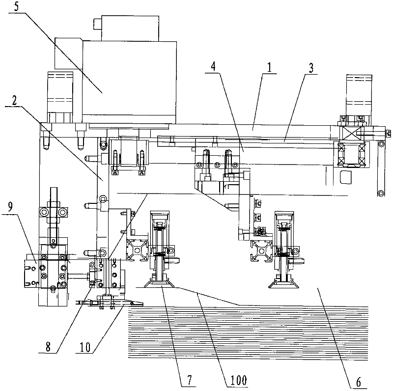
[0016] Please refer to the attached figure 1 to attach Figure 5 As shown, the present invention is a high-speed paper transfer device, which consists of an upper fixed plate 1, a support plate 2, a linear guide rail 3, a slider 4, a servo motor 5, a first paper suction nozzle combination 6, and a second paper suction nozzle combination 7. It is composed of horizontal sliding table cylinder 8, vertical sliding table cylinder 9 and paper presser foot 10 and other components.

[0017] Wherein, the linear guide rail 3 and the servo motor 5 are installed on the upper fixed plate 1 , and the support plate 2 is located below the upper fixed plate 2 . Further, a pair of lifting lugs 11 are also provided on the upper fixing plate 1, so as to facilitate the lifting of the paper delivery device.

[0018] The servo motor 5 drives the slider 4 through a timing pulley 51 , a tension pulley 52 and a timing belt 53 . A tension adjustment screw 12 is further provided at one end of the uppe...


PUM


Abstract

The invention relates to a high-speed paper-transferring device which comprises an upper fixing plate, a support plate, a straight-line guide rail, a slide block, a servo motor, a first paper suction nozzle combination, a second paper suction nozzle combination, a cross slipway air cylinder, a vertical slipway air cylinder and a paper pressing pin, wherein the straight-line guide rail and the servo motor are installed on the upper fixing plate and the support plate is located below the upper fixing plate; the slide block is driven by the servo motor through a synchronous belt wheel, a tension wheel and a synchronous belt; the slide block does reciprocating motions along the straight-line guide rail; the first paper suction nozzle combination is installed on the slide block and is driven by the slide block; the second paper suction nozzle combination is fixed on the support plate; the cross slipway air cylinder and the vertical slipway air cylinder are respectively installed on the support plate; and the paper pressing pin is connected with the cross slipway air cylinder. According to the high-speed paper-transferring device provided by the invention, a linear driving device is used for replacing a cam swing rod mechanism to drive the paper suction nozzle combinations to move, so that the paper-transferring device has the advantages of no mechanical impact, high paper-transferring speed and capability of realizing the optimized actions by each functional part.

Description

【Technical field】 [0001] The invention relates to a component part of a hot stamping machine or a die-cutting machine, in particular to a high-speed paper delivery device of a hot stamping machine or a die-cutting machine, and belongs to the technical field of printing equipment. 【Background technique】 [0002] The paper transfer device of the hot stamping machine or die-cutting machine in the prior art usually utilizes a cam mechanism to complete the entire paper transfer action. The mechanical paper transfer device has many defects such as large impact force, fast wear, and various action relationships that cannot be modified at any time, and each functional part cannot achieve optimal actions, and various disadvantages are prone to occur during the high-speed paper separation and paper transfer process. Meet the requirements of high-speed equipment. [0003] In order to solve the above technical problems, it is indeed necessary to provide a high-speed paper transfer devi...

Claims


Application Information

Patent Timeline
Patent Type & Authority Applications(China)
IPC IPC(8): B65H3/12
Inventor 黄金鹏徐景方张红川
Owner HEBEI YUTIAN XINGYE PRINTING MACHINERY
Why Eureka
Try Eureka