
Hybrid acoustic/electric signal converting device

A conversion device and electric signal technology, applied in printed circuits, electrical components, printed circuits, etc., can solve the problems of lowering product price competitiveness, difficulties in flexible management, and non-normal execution, and achieve the effect of improving price competitiveness

Inactive Publication Date: 2012-04-04
PILKOR CST
View PDF3 Cites 0 Cited by
  • Summary
  • Abstract
  • Description
  • Claims
  • Application Information

AI Technical Summary

Problems solved by technology

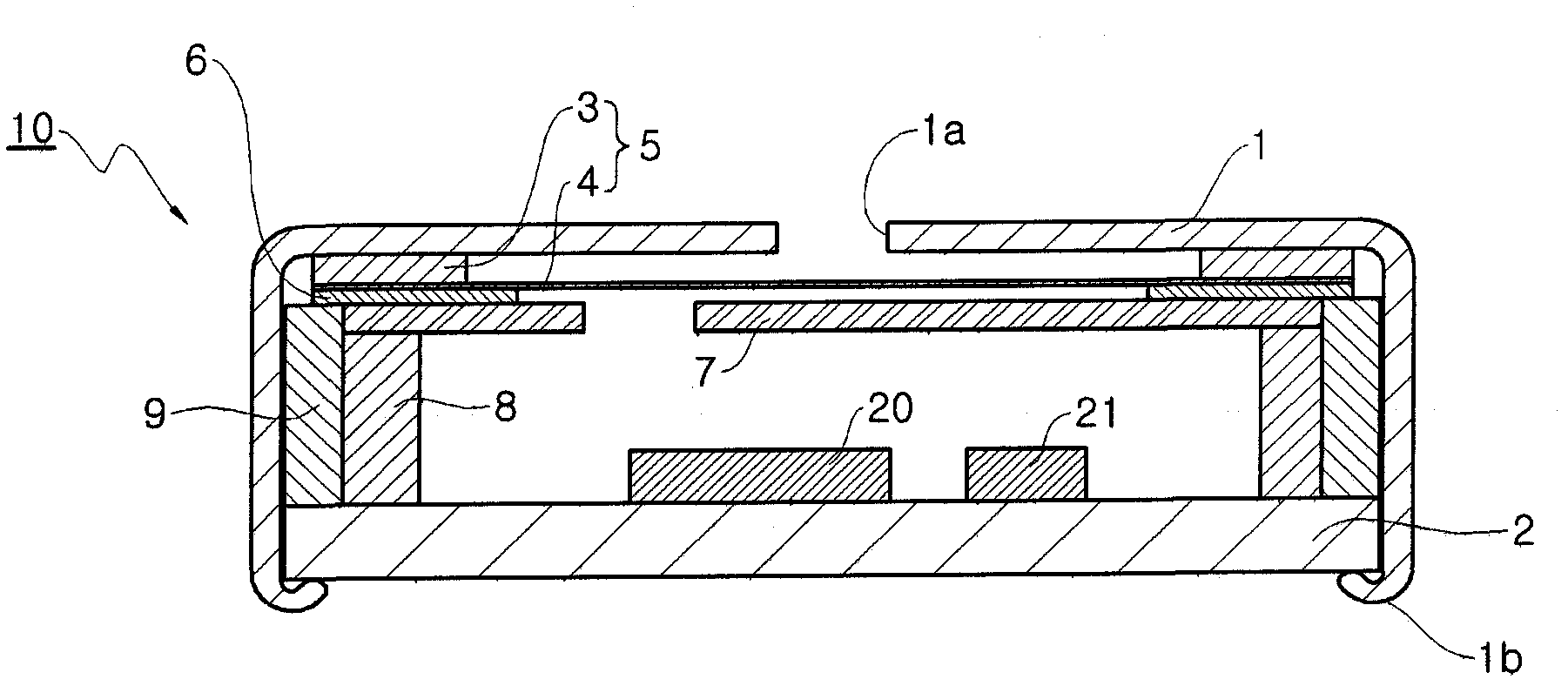
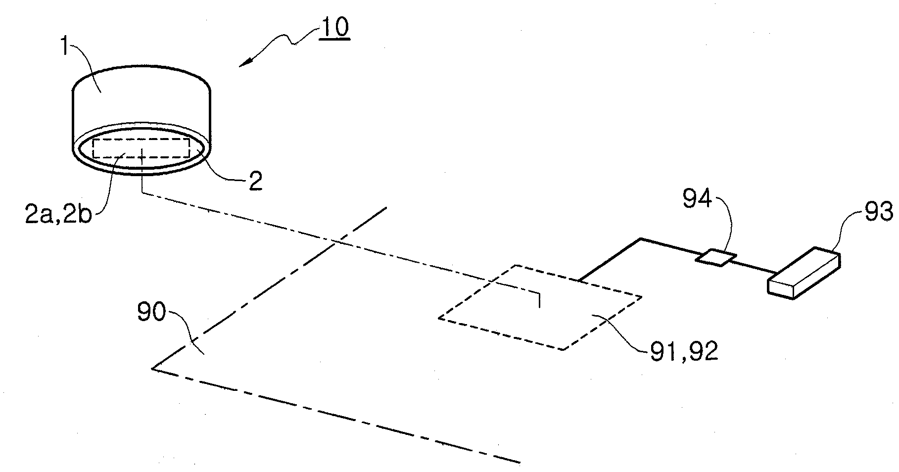
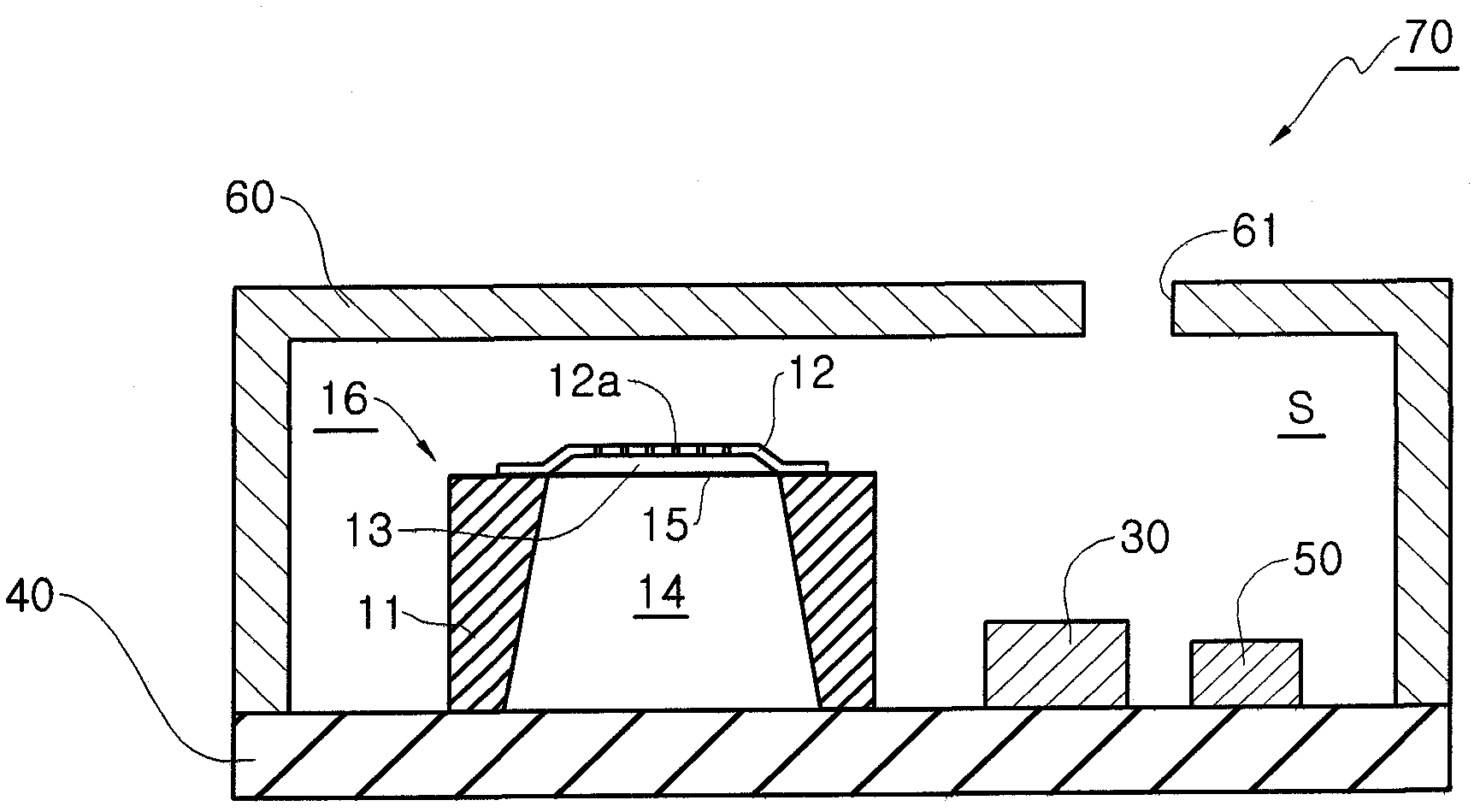
For this reason, the acoustic / electrical signal conversion package 70 may normally and correctly perform its own acoustic / electrical signal conversion function on the circuit board 80 having the power terminal 83 (in other words, on the circuit board for the package), but The acoustic / electrical signal conversion package 70 may not perform acoustically normally on a circuit board having no power supply terminal 83 but only a ground terminal 91 and an output signal receiving terminal 92 (in other words, on a circuit board for a microphone). / Electrical signal conversion function
As a result, the acoustic / electrical signal conversion package 70 may be limitedly mounted and operated only on the circuit board 80 of a specific electronic device (see figure 2 and Figure 4 )
[0019] If the acoustic / electrical signal conversion microphone 10 or the acoustic / electrical signal conversion package 70 is limited to operate only on a circuit board suitable for its own specific electronic device, the manufacturer (such as the manufacturer of the acoustic / electrical signal conversion microphone , Acoustic / electrical signal conversion packaging manufacturers, electronic device manufacturers, etc.) will feel great difficulties in flexible management of products, thereby seriously reducing the price competitiveness of their products

Method used


Image

  • Hybrid acoustic/electric signal converting device
  • Hybrid acoustic/electric signal converting device
  • Hybrid acoustic/electric signal converting device

Examples


Embodiment Construction

[0041] Embodiment of the invention

[0042] Hereinafter, the hybrid acoustic / electrical signal conversion device disclosed herein will be described in detail with reference to the accompanying drawings.

[0043] Such as Figure 5 and Figure 6 As shown, a hybrid acoustic / electrical signal conversion device according to an embodiment disclosed herein, such as a packaged hybrid acoustic / electrical signal conversion device 100, includes: an angular (or rectangular) covering container 110 with a sound inlet hole 111 the utensil 150 which is accommodated in the inner space of the covering container 110 and vibrates due to the sound input through the sound inlet hole 111; and the printed circuit board 190 which supports the covering container 110 and has a A circuit chip 191 (such as a FET chip) for capacitance variation caused by oscillation of the appliance 150 and a noise reduction element 192 (such as a capacitive element, an inductive element, a resistive element, etc.) for r...


PUM


Abstract

This disclosure is directed to implementing a measure of additionally including and installing a load register connected to a circuit chip in a printed circuit board so that the corresponding circuit chip may normally obtain and receive a series of operation powers by using the load register included in the printed circuit board; ; and a measure of additionally installing a ground terminal, a signal output terminal and a power receiving terminal to a joining portion of a printed circuit board joined to the circuit board of the electronic device, and electrically connecting both of the signal output terminal and the power receiving terminal to the load register and the circuit chip in the printed circuit board so that the corresponding load register and the circuit chip may normally obtain the operation power supplied from the electronic device by indirectly using the output signal receiving terminal and the signal output terminal.

Description

technical field [0001] The present invention relates to a hybrid acoustic / electrical signal conversion device, and more particularly to a method for making the final product on a microphone circuit board (or a circuit board without a power supply terminal) and package a circuit board (or a circuit without a load register) board) so that manufacturers (eg, acoustic / electrical signal conversion microphone manufacturers, acoustic / electrical signal conversion package manufacturers, electrical equipment manufacturers, etc.) can greatly improve their own products without any difficulty Competitively priced hybrid acoustic / electrical signal conversion device. Background technique [0002] In recent years, with the rapid development of technologies related to various electric / electronic devices such as information communication devices and sound devices, sound / electric signal conversion devices (such as sound / electric signal conversion Microphones, acoustic / electrical signal conver...

Claims


Application Information

Patent Timeline
Patent Type & Authority Applications(China)
IPC IPC(8): H04R23/00H05K1/02H04R1/02
CPCH05K1/023H05K2201/09027H05K1/181H04R1/04H04R3/00Y02P70/50
Inventor 郑甲烈
Owner PILKOR CST
Learn More