
Reactance type LED lighting current control circuit, driver and controlling system

A circuit and current technology, applied in the field of LED drive and control design, can solve the problems of complex LED drive implementation and unsuitable solar photovoltaic applications, and achieve the effect of improving power factor

Inactive Publication Date: 2014-12-24
孙善齐
View PDF8 Cites 0 Cited by
  • Summary
  • Abstract
  • Description
  • Claims
  • Application Information

AI Technical Summary

Problems solved by technology

[0006] At present, due to the fixed DC output voltage and line constraints, solar photovoltaic applications directly used for LED lighting are not adaptable; and adding an inverter design will complicate the implementation of LED drivers

Method used


Image

  • Reactance type LED lighting current control circuit, driver and controlling system
  • Reactance type LED lighting current control circuit, driver and controlling system
  • Reactance type LED lighting current control circuit, driver and controlling system

Examples


example

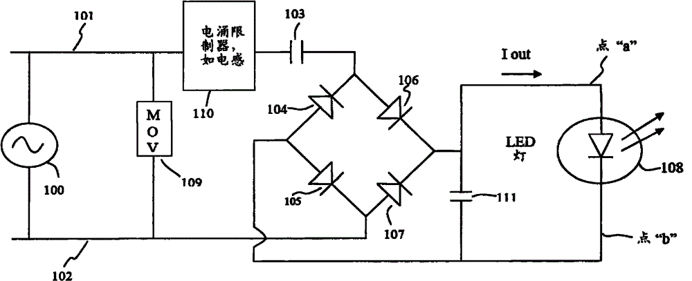
[0052] Example: A given LED light source, including multiple LED diodes, requires 300 mA of DC current to deliver the rated light output. Among them, the AC power supply is 120 volts, the frequency is 60 Hz, and the LED forward voltage drop is 20 volts. Substituting these values ​​into the parameters of the above formula (ie, Iout=300mA, f=60Hz, π is the circumference of the circle, and the LED forward voltage drop=20v), the value of the output capacitor 103 is 7.958 microfarads.

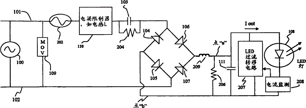
[0053] figure 1 The circuit only shows a part of the theoretical basis of the present invention; in order to make reactive current generation practical, more features and functions need to be added. figure 2 Therefore, a more complete circuit diagram is shown. In addition to MOV109, surge limiter 110 and filter capacitor 205, in order to prevent catastrophic failure of capacitor 103, a failure protection fuse or small-capacity resistor 202 is also added. In order to facilitate maintenance and safe ma...


PUM


Abstract

The invention discloses a novel AC LED lighting control / driving method which adopts a reactance component to produce required LED lighting current. Through the monitoring and protection function disclosed by the invention, the method can be efficient and practical and can be commonly used for all LED lighting applications based on alternate current.

Description

Technical field [0001] The present invention relates to the field of LED lighting, in particular to a new method and related solutions for realizing effective LED drive and control design in various fields. Background technique [0002] Common LED lighting drive / power supply always uses standard AC to DC conversion method for design, that is, off-line rectification is used, and energy storage is used to maintain the front-end circuit and the switching regulator connected to the rear to provide the LED with the required Drive (voltage drive or current drive). [0003] This design essentially involves EMI (electromagnetic interference) filtering to limit the bidirectional noise (including single mode and common mode) caused by entering the circuit domain and AC lines. The design also requires additional circuit components to protect fragile on-board electronics to prevent sudden power surges and interference that often exists in power lines and systems. Therefore, in a complete dri...

Claims


Application Information

Patent Timeline
Patent Type & Authority Patents(China)
IPC IPC(8): H05B37/02
Inventor 孙善齐
Owner 孙善齐
Learn More