
Method and device for implementing uplink power control

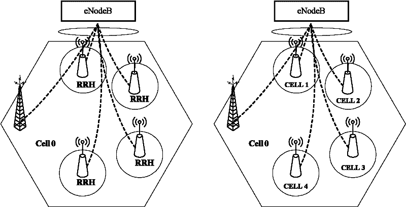
A power control and transmission power technology, applied in the field of communication, can solve problems such as difficult to guarantee the accuracy of uplink power control and imbalance of uplink and downlink transmission power

Active Publication Date: 2012-03-28
DATANG MOBILE COMM EQUIP CO LTD
View PDF2 Cites 29 Cited by
  • Summary
  • Abstract
  • Description
  • Claims
  • Application Information

AI Technical Summary

Problems solved by technology

[0007] Apparently, the current unbalance of uplink and downlink generating power makes it difficult to guarantee the accuracy of downlink path loss measurement and uplink power control

Method used


Image

  • Method and device for implementing uplink power control
  • Method and device for implementing uplink power control
  • Method and device for implementing uplink power control

Examples


Embodiment Construction

[0034] In the CoMp technology application scenario, in order to balance the uplink and downlink transmission power and improve the accuracy of uplink power control, in the embodiment of the present invention, the base station may notify the UE of the reference signal related information in advance, and the reference signal related information is used to indicate to the UE The reference signal used for downlink transmission path loss measurement; there are multiple transmitting ends of the reference signal, and the relevant information of the reference signal set corresponding to each transmitting end can be partly / all the same or completely different, and is managed by the base station in a unified manner. When it is determined which reference signals sent by the transmitting end need to be used for downlink transmission path loss measurement, the corresponding reference signal related information is sent to the UE, so that the UE performs downlink transmission path loss measure...


PUM


Abstract

The invention relates to the communication field, and discloses a method and a device for implementing uplink power control, which are used for balancing uplink and downlink transmission power and improving the accuracy of uplink power control. The method comprises the following steps that: a base station reasonably schedules UE (user equipment) to measure downlink transmission path loss according to a designated reference signal by means of relevant information of the reference signal; or the UE actively selects at least one of the received reference signals for measurement of the downlink transmission path loss, and then the UE carries out corresponding adjustment on the uplink transmission power thereof according to the measured result, namely open-loop uplink power control. Therefore, by adopting the method and the device, the downlink transmission path loss can be flexibly and accurately measured for one or more reference signal transmission ends according to the demand for path loss measurement so as to realize accurate uplink power control, which balances the uplink and downlink transmission power and improves the uplink power control accuracy.

Description

technical field [0001] The present invention relates to the communication field, in particular to a method and device for implementing uplink power control. Background technique [0002] RRH (Remote Radio Unit), also known as RRU, RRE, distributed antenna, etc., is a radio frequency unit separated from BBU (Baseband Processing Unit). Usually, RRH and BBU are placed in different geographical locations. The RRH includes radio frequency circuits, A / D converters, D / A converters, and optical transmission modules. The RRH is connected to the BBU through optical fibers. [0003] Distributed RRH is a network form using RRH networking. RRHs are scattered in a cell and can provide high-quality communication services to terminals because they are far away from terminals. Since the data of all RRHs in a cell are centrally processed by the BBU, it is possible to efficiently cooperate between RRHs, so distributed RRHs become an important scenario for CoMP (Coordinated Multipoint Transmis...

Claims


Application Information

Patent Timeline
Patent Type & Authority Applications(China)
IPC IPC(8): H04W52/14H04W52/18H04W52/24
CPCH04W52/146H04W52/24H04W52/18
Inventor 陈文洪高秋彬彭莹
Owner DATANG MOBILE COMM EQUIP CO LTD
Learn More