
Impedance matching method for gold bonding wire

A technology of gold wire bonding and impedance matching, which is applied in special data processing applications, instruments, electrical digital data processing, etc. , the effect of easy implementation

Inactive Publication Date: 2013-06-12
XIDIAN UNIV
View PDF4 Cites 0 Cited by
  • Summary
  • Abstract
  • Description
  • Claims
  • Application Information

AI Technical Summary

Problems solved by technology

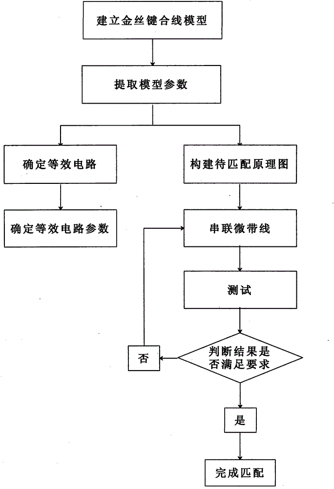
[0008] In order to overcome the deficiencies of the above-mentioned prior art, a gold wire bonding wire impedance matching method is proposed for the gold wire bonding wire mismatch problem, and a gold wire bonding wire model is established, by adding 2-4 sections of microstrip line to Gold wire bonding model is compensated to obtain a simple and easy matching network

Method used


Image

  • Impedance matching method for gold bonding wire
  • Impedance matching method for gold bonding wire
  • Impedance matching method for gold bonding wire

Examples


Embodiment Construction

[0028] Refer to the attached figure 1 The present invention is further described.

[0029] At present, many circuit simulation software provide very good fast algorithms, model extraction and intuitive operation platforms, such as HFSS, microwave office, Designer, ADS, CST, etc. The embodiment of the present invention adopts microwave circuit simulation design software ADS to establish physical model, equivalent network and design matching network.

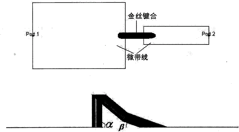
[0030] (1) Establish the gold wire bonding model: use ADS to calculate the width of the 50Ohm microstrip line to be 0.386mm, and then establish the left end as the 50Ohm microstrip line and the right end as the 0.1mm microstrip line in the layout (because it can be processed in engineering The thinnest wire is 0.1mm), the distance between the two microstrip lines is 4mil, and the interface between the gold wire and the microstrip line is 1mil, so the length of the gold wire is 6mil .In this model, the gold wire bonding wire adop...


PUM


Abstract

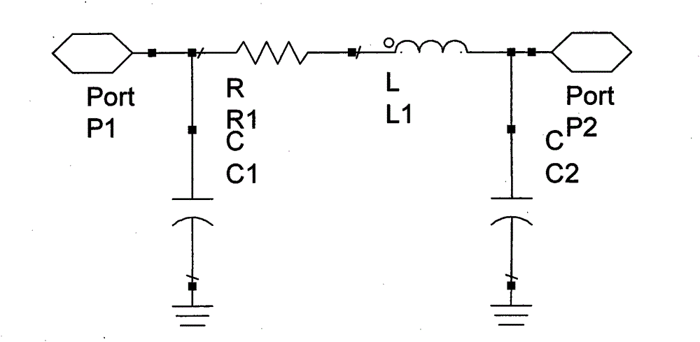
The invention discloses an impedance matching method for a gold bonding wire. The method comprises the following steps: establishing a gold bonding wire model; extracting model parameters in a circuit application frequency band; causing the gold bonding wire model to be equivalent to a TT-shaped low-pass filter network; fitting equivalent network parameters by using the extracted model parameters; and introducing the extracted model parameters into a to-be-matched schematic diagram and adding a Smith chart matching control. In the Smith chart, 2-4 sections of micro-strip wires are serially connected so as to establish a matching network; a load impedance is converted into an actual impedance by first to second sections; the actual impedance is converted into a source impedance by a third section which is a Lambda / 4 converting wire, thereby achieving impedance matching; and a fourth section is a gradual changing wire used for transition. The impedance matching method has the advantagesof simple design concept, easiness in application, capability of saving a circuit board space, small frequency limitation, wide frequency band width and excellent compensation effect. The impedance matching method is used for interconnecting monolithic microwave integrated circuits, coplanar waveguides, microwave transmission lines or RF (Radio Frequency) grounding sides.

Description

technical field [0001] The invention belongs to the technical field of electronic engineering, and further relates to an impedance matching method of a gold wire bonding wire in the field of microwave circuit and chip packaging. The invention can be used for the interconnection of monolithic microwave integrated circuits (MMICs), coplanar waveguides, and the interconnection between microwave transmission lines or with RF ground planes, and can accurately extract the parameters of the gold wire bonding wire model, and perform gold wire bonding according to the parameters. Equivalent circuit design and impedance matching network design of bonding wire. Background technique [0002] In radio frequency and microwave circuits, gold wire bonding wires are often used to realize the interconnection of components such as monolithic microwave integrated circuits (MMICs), lumped resistors and capacitors, microstrip lines, coplanar waveguides, and between microwave transmission lines or...

Claims


Application Information

Patent Timeline
Patent Type & Authority Patents(China)
IPC IPC(8): G06F17/50
Inventor 侯建强王瑞华李鹏杰牛中奇卢智远李平文远钱帮龙邓敬亚
Owner XIDIAN UNIV
Learn More