
Overburden pressure system for three-dimensional model

A three-dimensional model and overburden technology, which is applied in the fields of production fluids, wellbore/well components, and earthwork drilling, etc., can solve the problems of large dead volume, experimental data errors, jumping flow, etc., and achieve the effect of ensuring the experimental accuracy.

Inactive Publication Date: 2012-03-28
南通市飞宇石油科技开发有限公司
View PDF6 Cites 6 Cited by
  • Summary
  • Abstract
  • Description
  • Claims
  • Application Information

AI Technical Summary

Problems solved by technology

[0006] 1. Generally, large-scale three-dimensional models do not have a pressure cavity design. After sand filling in the internal space of the model, the inner end face of the flange and the sand filling layer in the inner circumferential wall space of the model cannot be in good contact. The sand filling layer is relatively loose, and it is easy to The formation of subsidence and jump flow is very different from the real stratum, which causes errors in the experimental data and affects the authenticity of the experiment
[0007] 2. Since the sand filling layer cannot be compacted, the gap between the sand filling layer and the flange and the cylinder has a large dead volume, and the experimental data does not match the actual production of the oil field.
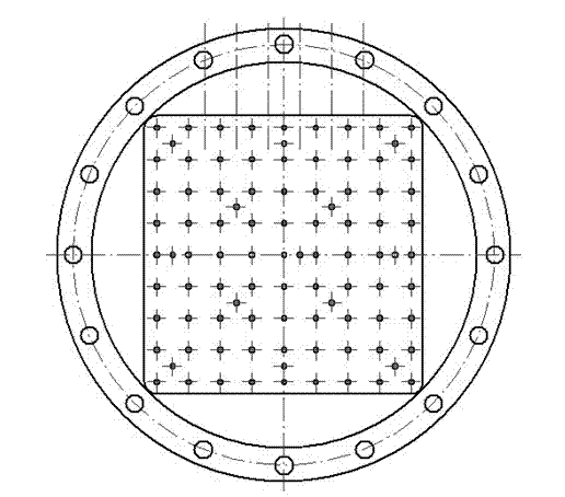
The traditional method is to use the cylinder model to do experiments, which is not convenient and realistic for the simulated ground well layout. The real ground area uses a square model to arrange the well pattern with the five-point method, nine-point method or matrix method

Method used


Image

  • Overburden pressure system for three-dimensional model
  • Overburden pressure system for three-dimensional model
  • Overburden pressure system for three-dimensional model

Examples


Embodiment Construction

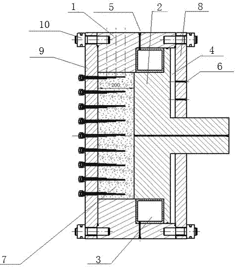
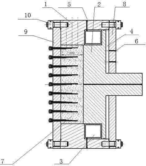
[0019] like figure 1 As shown, the three-dimensional model overburden system of the present invention includes a cylinder body 1, a piston 2 disposed in the cylinder body 1, a sand filling layer 7 connected to the piston 2, and an upper flange 8 and a lower flange for connection. 9 and fastening bolts 10, the piston is composed of a square piston and a circular piston, four half-moon-shaped capsule chambers 3 are arranged between the piston 1 and the cylinder body 2, and the capsule chamber 3 is located at the intersection of the square piston and the circular piston , One side of the cylinder body 1 is provided with a circular pressure chamber 4, the capsule chamber 3 is connected with a capsule chamber injection port 5, and the circular pressure chamber 4 is connected with a pressure chamber injection port 6.

[0020] During work, the hydraulic pump injects liquid to pressurize the overburden chamber 4, and the piston 2 compresses the sand filling layer 7, so that the sand f...


PUM


Abstract

The invention provides an overburden pressure system for three-dimensional model, comprising a barrel body, a piston disposed in the barrel body and a sand filling layer connected with the piston; the piston is composed of a square piston and a round piston; a capsule chamber is disposed between the piston and the barrel body; the capsule chamber is located at the junction of the square piston and the round piston; one side of the barrel body is provided with a round overburden pressure chamber; the capsule chamber is connected with a capsule chamber injecting opening; the round overburden pressure chamber is connected with an overburden pressure chamber injecting opening. The invention has the following technical effects: 1, a round overburden pressure chamber is provided, a hydraulic pump is used for injecting liquid and pressurizing the overburden pressure chamber; the piston is used for pressing the sand filling layer, so that the sand filling layer has the overburden pressure function, then then experimental precision and accuracy are ensured; 2, four blocks of semilunar capsule chambers (rubber material) are arranged between the piston and the barrel body, when the piston is pressed down, liquid is injected into the capsule chamber by the capsule chamber injecting opening; the shape of the rubber capsule is changed by the liquid pressure, so as to fill the gap and remove the dead volume between the barrel body and the piston.

Description

technical field [0001] The invention relates to a simulation device, in particular to a three-dimensional model covering pressure system. Background technique [0002] "3D model overburden pressure system" is a set for simulating reservoir temperature, pressure, formation dip angle, plane and vertical heterogeneity, water flooding, polymer flooding, three recovery injection agents, etc. regular influence device. This configuration is mainly used to simulate the distribution of remaining oil in the process of water injection development under the conditions of large well spacing, multi-layer commingled production, and heavy oil reservoirs. [0003] The 3D model simulation test is mainly used to simulate the influence of injection-production well pattern, interlayer heterogeneity and plane heterogeneity on the distribution of remaining oil. Generally, the physical simulation experiment of displacement oil production is carried out under the temperature and pressure of th...

Claims


Application Information

Patent Timeline
IPC IPC(8): E21B43/22E21B43/20
Inventor 邰九龙许文革王刚涛
Owner 南通市飞宇石油科技开发有限公司
Learn More