Method and circuit for detecting alternating-current fuse failure of uninterruptible power supply

A fault detection and voltage detection technology, applied in circuit breaker testing and other directions, can solve problems such as easy misjudgment of AC fuse failure, failure to detect small current of AC fuse fault, etc. The effect of alarming problems and improving reliability

Active Publication Date: 2014-06-04
INVT POWER SYST SHENZHEN CO LTD
View PDF5 Cites 1 Cited by
  • Summary
  • Abstract
  • Description
  • Claims
  • Application Information

AI Technical Summary

Problems solved by technology

[0003] In view of the above-mentioned shortcomings of the AC insurance failure detection method of the uninterruptible power supply in the prior art mentioned above, the present invention provides a new method and circuit for the AC insurance failure detection of the uninterruptible power supply. The voltage difference between terminals can be used to determine whether the AC fuse is faulty, and at the same time, it solves the problem that the AC fuse fault cannot be detected when the thyristor fails and the fault of the AC fuse is easily misjudged when the thyristor is faulty.

Method used


Image

  • Method and circuit for detecting alternating-current fuse failure of uninterruptible power supply
  • Method and circuit for detecting alternating-current fuse failure of uninterruptible power supply
  • Method and circuit for detecting alternating-current fuse failure of uninterruptible power supply

Examples


Embodiment Construction

[0017] This embodiment is a preferred implementation mode of the present invention, and other principles and basic structures that are the same or similar to this embodiment are within the protection scope of the present invention.

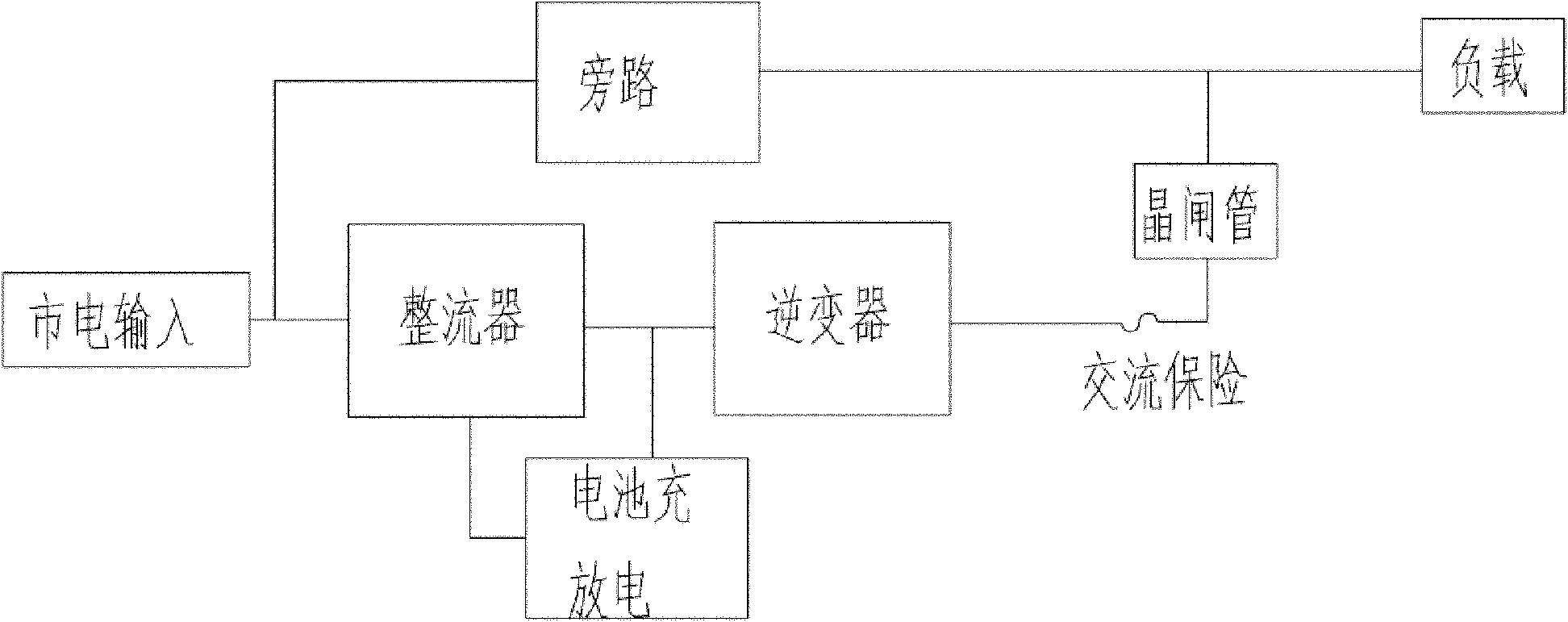
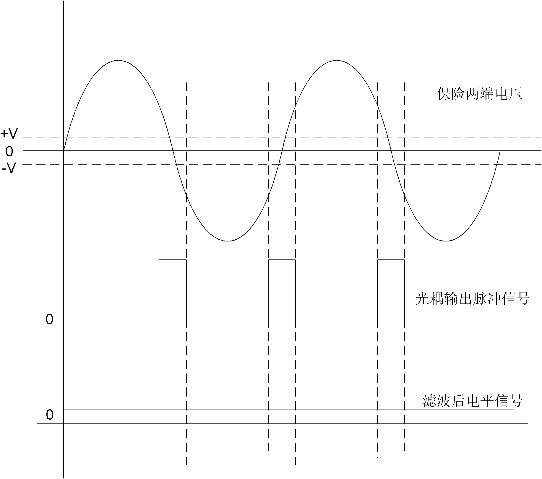
[0018] Please see attached figure 2 , the circuit in the present invention mainly includes a voltage detection module, a switch module, a filter module, a voltage regulator tube and a switch tube. In this embodiment, the voltage detection module includes two branches connected in reverse parallel, and the first branch includes Resistor R1, capacitor C1 and the primary side of the first optocoupler connected in series (that is, the light-emitting diode in the optocoupler), the second branch includes resistor R2 connected in series, capacitor C2 and the primary side of the second optocoupler, two The two ends of each branch are respectively connected to the two ends of the AC insurance to be detected, and the directions of the light-emitting diodes...


PUM


Abstract

The invention discloses a method and circuit for detecting alternating-current fuse failure of an uninterruptible power supply. The method comprises the steps of: detecting voltages at two ends of an alternating-current fuse by using a voltage detection module, when a larger voltage difference exists at two ends of the alternating-current fuse, controlling a switch module to output a low-voltage alternating-current signal, when the voltage difference at two ends of the alternating-current fuse is close to zero, controlling the switch module to output a high-voltage direct-current signal, outputting a signal by the switch module and rectifying, and then controlling the action of a switch tube by a serially-connected voltage-stabilizing tube, and outputting an alternating-current fuse state signal by the switch tube. The corresponding circuit is characterized in that two optical couplers are reversely connected to two ends of the alternating-current fuse in parallel, and secondary sides of the optical couplers are connected in parallel and connected between a positive power supply and ground to be used as the switch module. The invention avoids the problem of false alarm common in the traditional failure detection method. Meanwhile, the invention can be used for detecting the failure of the alternating-current fuse before an inverter carries a load, and avoids that the inverter carries the load under the failure condition.

Description

technical field [0001] The invention discloses an AC insurance fault detection method and a circuit, in particular to an uninterruptible power supply AC insurance fault detection method and a circuit, belonging to the technical field of power electronic conversion. Background technique [0002] Uninterruptible power supply, referred to as UPS (Uninterruptible Power Supply), has been widely used in people's lives and has long been common. Please see attached figure 1 , the common structure of uninterruptible power supply in the prior art is as figure 1 shown, and will not be repeated here. AC insurance is a protection device commonly used in uninterruptible power supplies. It is often used to protect the uninterruptible power supply from disconnecting the fault point in the case of abnormally large current, and to protect the power supply. For example, when the inverter or thyristor in the main circuit is short-circuited At this time, if the bypass is turned on, the ener...

Claims


Application Information

Patent Timeline
Patent Type & Authority Patents(China)
IPC IPC(8): G01R31/327
Inventor 夏小荣
Owner INVT POWER SYST SHENZHEN CO LTD
Why Eureka
Try Eureka