High-precision controllable microscanning device based on piezoelectric ceramics and sliding guide rail

A piezoelectric ceramic and sliding guide technology, applied in the field of high-precision controllable micro-scanning devices, can solve the problems of low movement accuracy and poor direction consistency, and achieve the effects of high displacement repeatability, ensuring consistency and reducing friction.

Inactive Publication Date: 2012-03-21
BEIJING INSTITUTE OF TECHNOLOGYGY
View PDF5 Cites 6 Cited by
  • Summary
  • Abstract
  • Description
  • Claims
  • Application Information

AI Technical Summary

Problems solved by technology

[0008] The purpose of the present invention is to propose a high-precision controllable micro-scanning device based on piezoelectric ceramics and sliding guide rails to solve the problems of low movement accuracy and poor direction consistency in existing optical micro-scanning mechanisms

Method used


Image

  • High-precision controllable microscanning device based on piezoelectric ceramics and sliding guide rail
  • High-precision controllable microscanning device based on piezoelectric ceramics and sliding guide rail
  • High-precision controllable microscanning device based on piezoelectric ceramics and sliding guide rail

Examples


Embodiment Construction

[0034] The present invention will be further described below in conjunction with the accompanying drawings and embodiments.

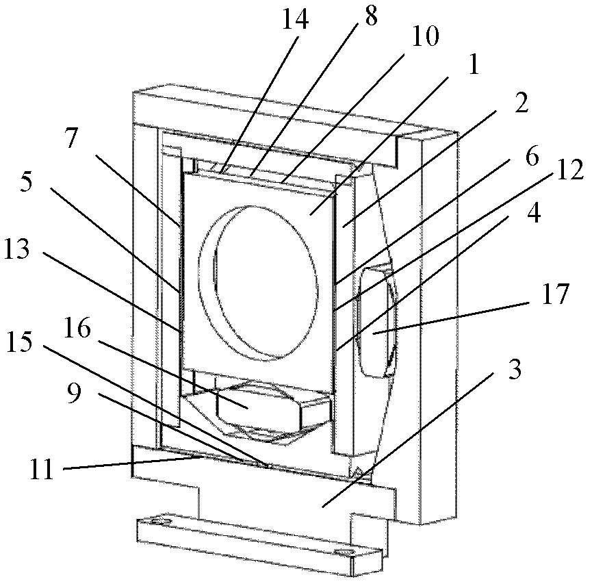
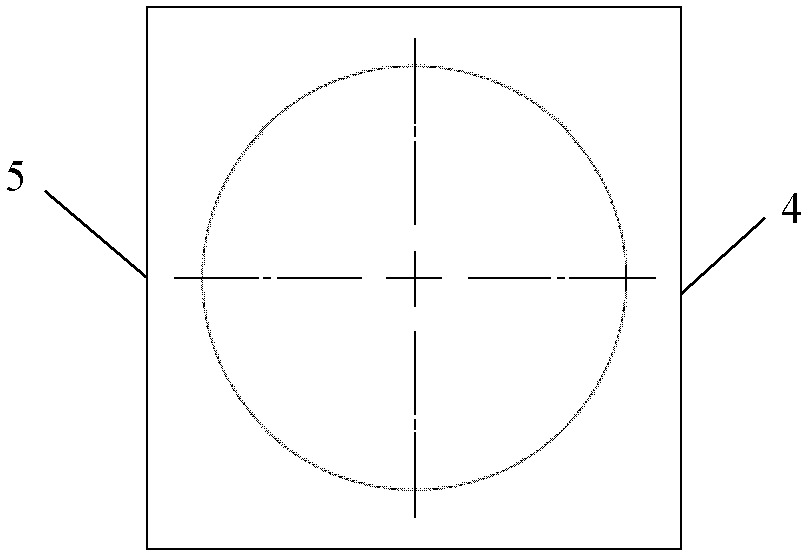
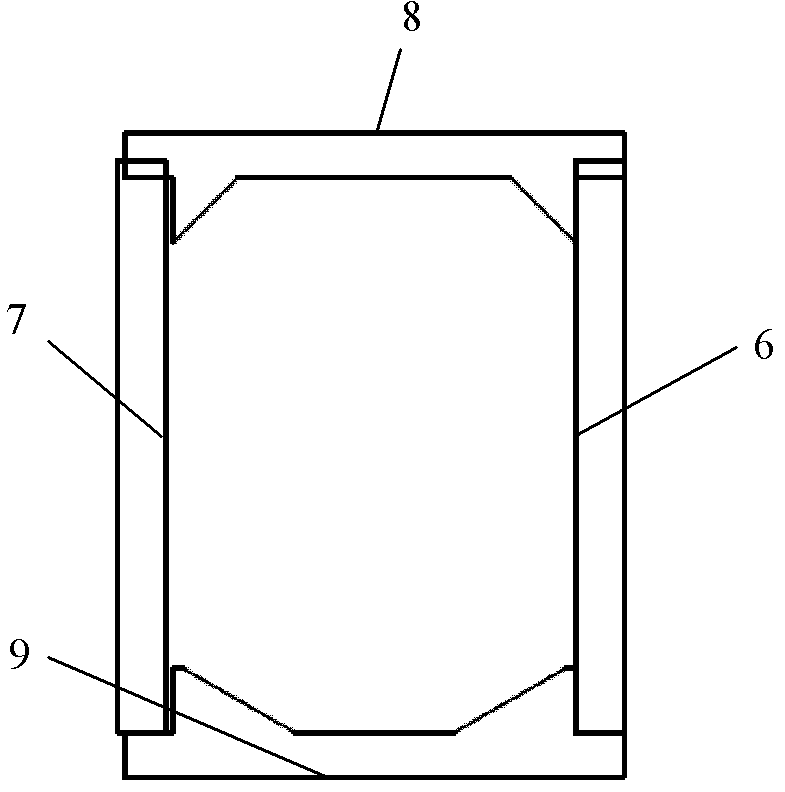
[0035] A high-precision controllable micro-scanning device based on piezoelectric ceramics and sliding rails, such as figure 1As shown, the vertical moving frame 1, the horizontal moving frame 2, the micro scanning mechanism frame 3, the first vertical dovetail slot 4, the second vertical dovetail slot 5, the third vertical dovetail slot 6, the fourth vertical dovetail slot 7, the first horizontal Dovetail groove 8, second horizontal dovetail groove 9, third horizontal dovetail groove 10, fourth horizontal dovetail groove 11, first ball 12, second ball 13, third ball 14, fourth ball 15, first piezoelectric ceramic 16. The second piezoelectric ceramic 17;

[0036] Wherein, the first piezoelectric ceramic 16 is used to drive the vertically movable frame 1, and the second piezoelectric ceramic 17 is used to drive the horizontally movable frame 2; the firs...


PUM


Abstract

The invention relates to a design method of a high-precision controllable microscanning mechanism based on piezoelectric ceramics and a sliding guide rail, which belongs to the field of the design of high-performance photoelectronic imaging systems. By utilizing the relation that the expansion amounts of the piezoelectric ceramics are in proportion to driving voltages of the piezoelectric ceramics, the invention provides the high-precision controllable microscanning mechanism which uses the piezoelectric ceramics as driving devices and uses the sliding guide rail as a translation element to control the marching direction. The mechanism comprises two piezoelectric ceramics, a vertical movable framework, a horizontal movable framework, four pairs of dovetail grooves, a microscanning mechanism framework and four groups of balls. The piezoelectric ceramic for realizing displacement driving in the vertical direction is connected with a two-dimensional translation element and is arranged atthe inner part of a vertical sliding guide rail component. The piezoelectric ceramic for realizing displacement driving in the horizontal direction is connected with the outer wall of the microscanning mechanism and the vertical sliding guide rail component to realize horizontal displacement driving. The displacement amounts of the piezoelectric ceramics can be controlled in a high-precision manner through the amplitude values of the driving voltages.

Description

technical field [0001] The invention relates to a high-precision controllable micro-scanning device based on piezoelectric ceramics and sliding guide rails, belonging to the field of photoelectric imaging system design. Background technique [0002] As a cutting-edge technology that converts invisible infrared radiation energy into visible grayscale images, infrared thermal imaging technology uses detectors sensitive to infrared radiation to detect differences in infrared radiation between different objects or between different positions on the surface of objects. To obtain the radiation energy distribution of the infrared scene, so as to achieve the purpose of imaging the infrared scene. Due to the characteristics of concealment, passivity and all-weather application of infrared thermal imaging technology, it has extremely high military strategic application prospects and demands. With the continuous improvement of infrared technology theory, the continuous maturity of sem...

Claims


Application Information

Patent Timeline
IPC IPC(8): G01J5/00
Inventor 金伟其刘斌王霞徐超陈伟力陈艳刘崇亮
Owner BEIJING INSTITUTE OF TECHNOLOGYGY
Why Eureka
Try Eureka