
Flameless trapped vortex burner for gas turbine

A burner and vortex technology, which is applied to gas fuel burners, burners, combustion methods, etc., can solve the problems of low combustion noise, noise and pressure fluctuations, and achieve low combustion noise, small pressure fluctuations, and complete fuel combustion Effect

Active Publication Date: 2013-07-31
中科合肥中型燃气轮机研究院有限公司
View PDF9 Cites 3 Cited by
  • Summary
  • Abstract
  • Description
  • Claims
  • Application Information

AI Technical Summary

Problems solved by technology

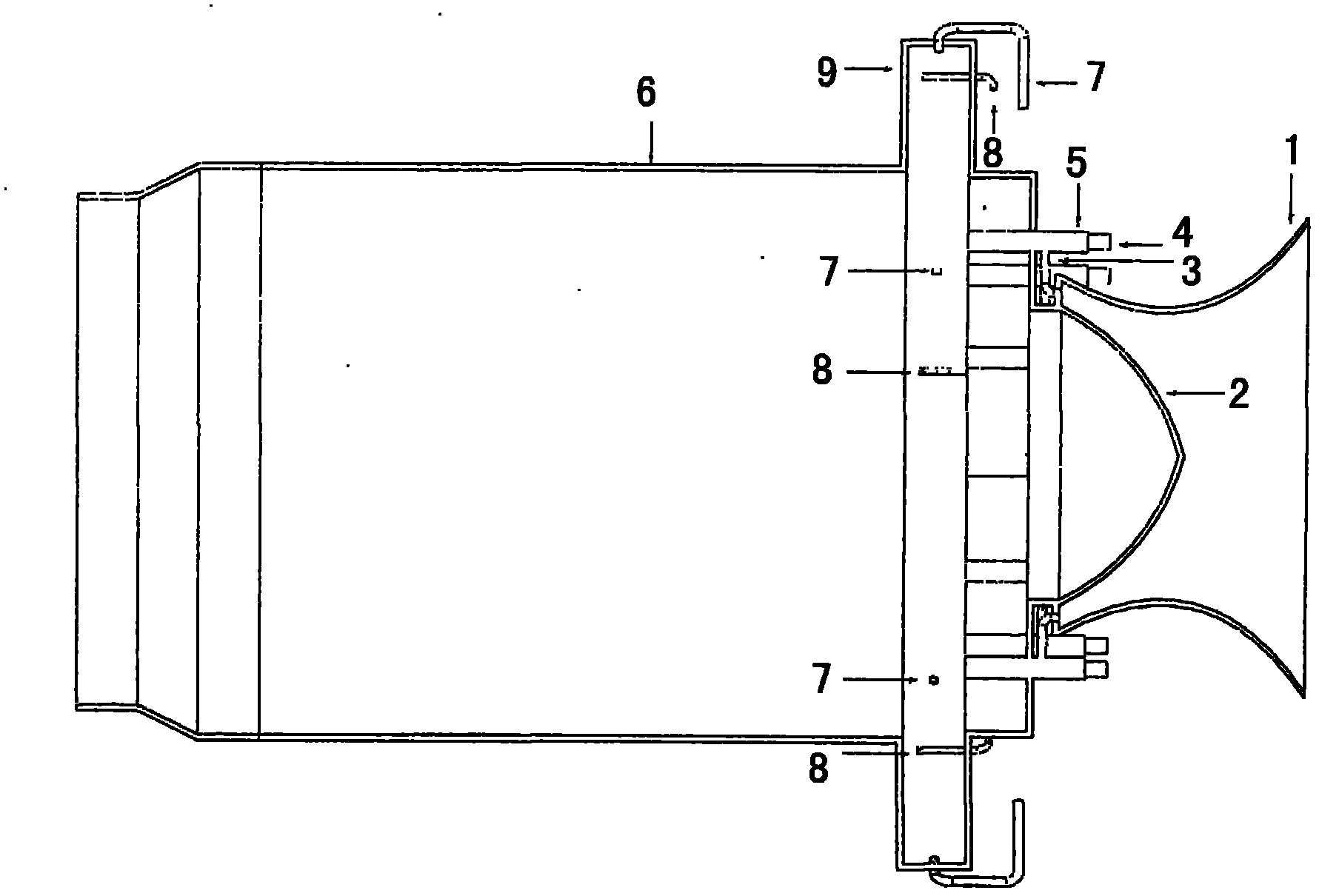
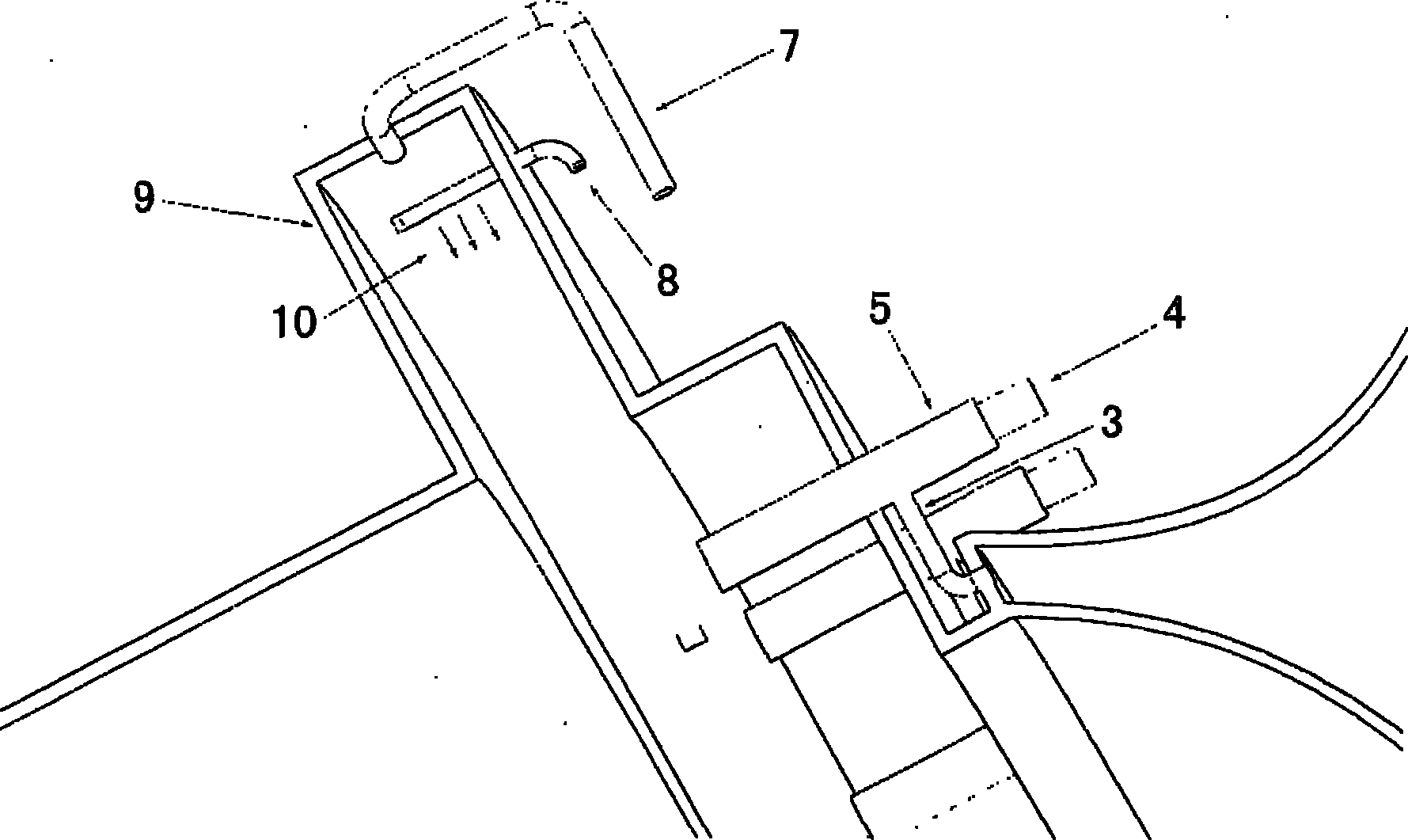
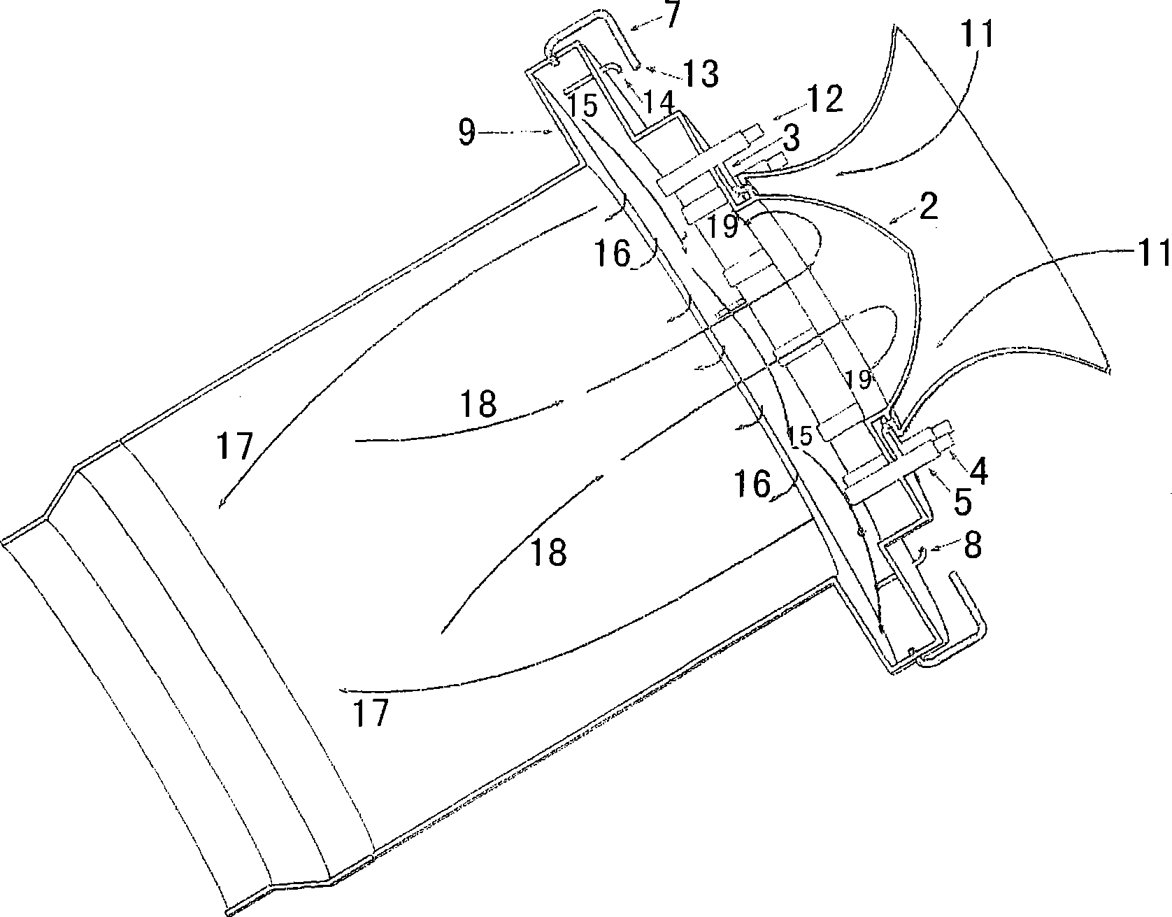
[0010] The purpose of the present invention is to disclose a flameless vortex burner for a gas turbine, which combines the flameless combustion technology and the vortex cavity combustion technology to overcome some shortcomings of the flameless combustion itself. The influence of concentration is great; at the same time, it solves the problems of noise and pressure fluctuation that are easy to generate in the concave cavity of the vortex; and maintains the advantages of flameless combustion and vortex combustion, with low combustion noise, low NOx and CO emissions, stable and wide combustion range

Method used


Image

  • Flameless trapped vortex burner for gas turbine
  • Flameless trapped vortex burner for gas turbine
  • Flameless trapped vortex burner for gas turbine

Examples


Embodiment Construction

[0037] In a flameless vortex burner of a gas turbine according to the present invention, the existence of the duty flame in the concave cavity can greatly reduce the lean oil flameout equivalent ratio of the flameless combustion, even if the amount of oil is small, the high-temperature flue gas produced by the duty flame, It can also ensure the high temperature and low oxygen atmosphere of the oxidant, and maintain flameless combustion.

[0038] In the present invention, the cavity of the flame stabilizer with a trapped vortex cavity is in an annular structure, and its cross section is perpendicular to the axial direction, and is located downstream of the main flow gas inlet of the combustion chamber. 6 low-velocity air injection pipes and 6 low-velocity fuel nozzles are arranged around the concave cavity. The air injection direction is at an angle of 15 degrees to the horizontal direction. The duty flame in the hour cavity is not affected. The fuel in the vortex combustion c...


PUM


Abstract

The invention relates to a flameless trapped vortex burner for a gas turbine, which combines a flameless combustion technology and a trapped vortex combustion technology. By utilizing the advantages of small pressure fluctuation and small noise of the flameless combustion technology, the defect of large noise of the trapped vortex combustion technology is overcome; as on-duty flame, trapped vortex combustion can further reduce the flameout equivalence ratio of the flameless combustion by utilizing the advantages of compact volume and stable combustion of the trapped vortex combustion technology; and generated high-temperature flue gas can be used for diluting and heating fresh mixed gas and broadening the stable combustion scope of the flameless combustion. The burner simultaneously has the advantages of the flameless combustion technology and the trapped vortex combustion technology and has uniform temperature field, low pollutant discharge and good combustion stability.

Description

technical field [0001] The invention relates to gas turbine combustion chamber technology, which is a combination of flameless combustion and vortex concave cavity combustion, and realizes the burner structure of the two combustion technologies at the same time. Background technique [0002] As the most widely used power machinery for human beings, gas turbines have penetrated into all major economic sectors. The wide application fields involve sea, land and air, and the service objects benefit military and civilian use. The development of high-performance, stable and low-pollution gas turbine combustors will always be The goal pursued by gas turbine researchers. At present, the ultra-low pollution combustion technologies for high-performance gas turbine combustors mainly include: Rich burn, Quick quench, Lean burn (RQL for short), Lean Premixed Prevaporized (LPP for short) ), lean premixed direct injection combustion (Lean Direct Injection referred to as LDI) and so on. ...

Claims


Application Information

Patent Timeline
Patent Type & Authority Patents(China)
IPC IPC(8): F23D14/02F23D14/26F23D14/46
Inventor 毛艳辉徐纲房爱兵崔玉峰
Owner 中科合肥中型燃气轮机研究院有限公司
Learn More