
Free combined vehicle, combination unit and combination connector

A combined unit and combined vehicle technology, applied to bicycles, bicycle saddles, bicycle accessories, etc., can solve problems such as low inertia, unstable use, and poor structural safety

Inactive Publication Date: 2012-03-21
陈冀鲁
View PDF6 Cites 1 Cited by
  • Summary
  • Abstract
  • Description
  • Claims
  • Application Information

AI Technical Summary

Problems solved by technology

However, the structures of the front and rear wheels of the bicycle are not stable during use, so that some people can't use them, and some people dare not use them, especially when using the saddle for a long time, it is easy to make people tired
Although the design of four-wheeled bicycle has been arranged in recent years, as can refer to Chinese utility model patent instruction ZL00202924.3 and ZL01238542.5, all because of various reasons such as volume, structure, function, price and the production equipment of parts, investment, be difficult to popularize
[0003] In addition, in the current means of transportation on land, the axles of carriages and trolleys are fixed on the car body with parallel wheels, but the wheels are passive wheels and cannot be used as driving wheels (that is, driving wheels); the rear wheels of bicycles can be used as driving wheels. , but the safety of the front and rear rounds is relatively poor; the tricycle is a single-wheel drive mode, with large resistance and small inertia; Large, high cost of use; trains need special tracks, and they have to go up and down at fixed times and places, and they cannot be used for random travel

Method used


Image

  • Free combined vehicle, combination unit and combination connector
  • Free combined vehicle, combination unit and combination connector
  • Free combined vehicle, combination unit and combination connector

Examples


Embodiment Construction

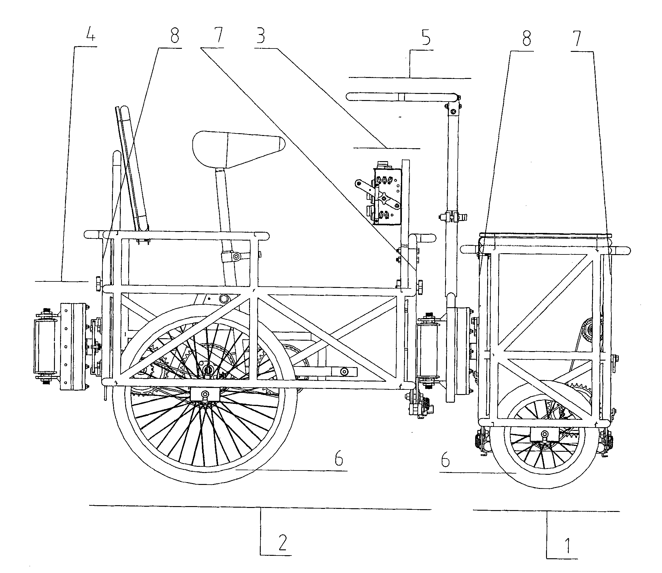
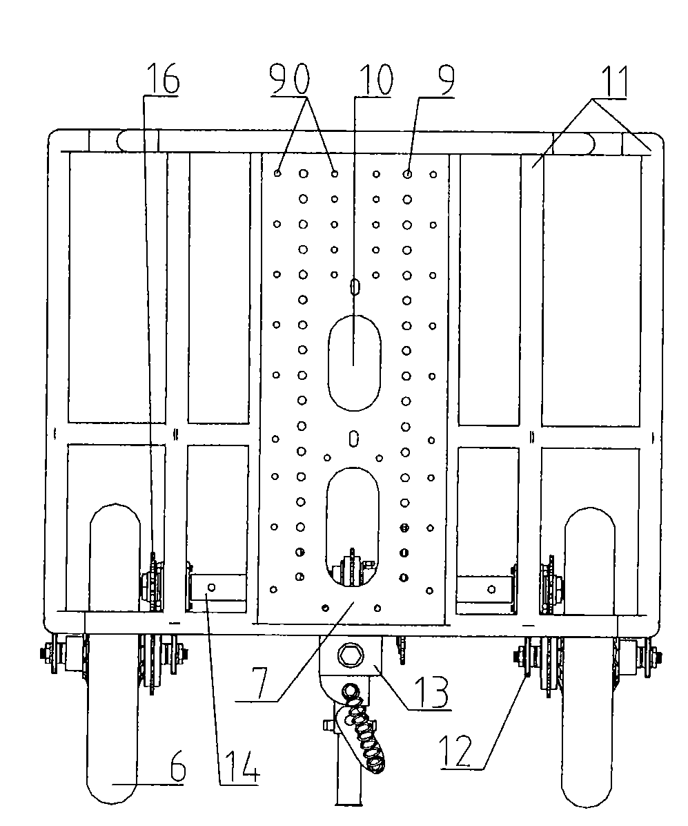
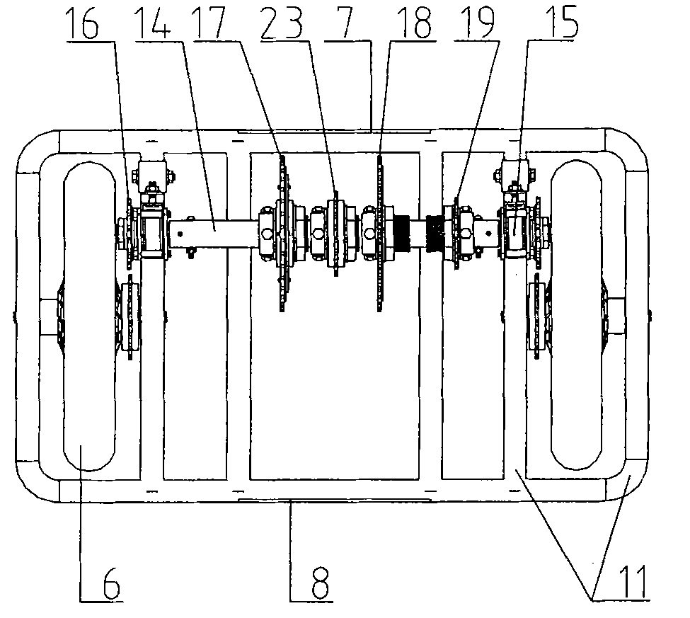
[0054] The combined car of the present invention should be combined into one by more than two combined units (comprising supporting units) to run smoothly. For combination, a connection plate with bolt connection holes is provided at the front or rear of the combination unit, or a connection plate with bolt connection holes is provided at the front and rear, so that the combination unit can be combined into a combination car by using a combination connector or directly .

[0055] figure 1 A two-unit combination vehicle of the present invention is shown. Combination unit 2 among them is main vehicle (drive combination unit); combination unit 1 is auxiliary vehicle (driven combination unit). exist figure 1 In the embodiment shown, the combination units 1 , 2 each have a front connecting plate 7 and a rear connecting plate 8 at their front and rear. But when using as figure 1 During the combined mode of the combined car shown, the combined unit 1 as the auxiliary vehicle als...


PUM


Abstract

The invention relates to a free combined vehicle, combination units and a combination connector. The combination units of the free combined vehicle comprises a vehicle body frame and two wheels, wherein the two wheels are mounted on left and right wheel axle fixing plates of the vehicle body frame in parallel; connecting plates, which are connected to another combination unit, are arranged in front of or / and behind the vehicle body frame; a parallel driving rod which is provided with a flywheel and a gear is mounted on a bearing bracket in the vehicle body frame; and chain transmission is utilized to drive flywheels or gears on the two wheels, thereby synchronously driving the two parallel wheels. The combination connector comprises a fixed connecting plate, a steering shaft, a steering plate, a sliding part, a sliding shaft and a moveable connecting plate capable of forwards and backwards rotating on the sliding shaft. The combination connector has various adjusting functions. Manpower and dynamic power of two driving modes are adopted in the combined vehicle, of which the types can be conveniently and freely selected by people. The combination connector and quick connecting accessories can be used for quickly combining and disassembling the combined vehicle. The free combined vehicle can be used at will, is suitable for different roads, is simple in structure and is suitable for city and countryside.

Description

technical field [0001] The invention relates to a combination unit of a combination vehicle, which is mainly composed of a vehicle body frame and two wheels; the invention also relates to a combination connector and a combination vehicle using the combination connector to combine the combination units together. Background technique [0002] The British have invented bicycles for more than 150 years. The rapid development of electric bicycles has proved that the simple, convenient and environmentally friendly design of bicycles is suitable for future development. But the structure of each round before and after the bicycle is not stable when in use, so that some people can't use it, and some people dare not use it, especially when using the saddle for a long time, it is easy to make people tired. Though the design of four-wheeled bicycle is arranged in recent years, as can refer to Chinese utility model patent description ZL00202924.3 and ZL01238542.5, all are difficult to po...

Claims


Application Information

Patent Timeline
IPC IPC(8): B62K17/00B62M1/02B62M9/02B62J1/10B62M1/36
Inventor 陈冀鲁
Owner 陈冀鲁
Learn More