Array type flexible force sensor

A flexible force and array-type technology, applied in the field of array-type flexible force-sensing sensors, can solve the problems that the surface microscopic shape is easily damaged by pressure, the sensor has a large difference in the initial resistance, and the roughness of the contact surface is difficult to achieve small hysteresis and extended The effects of longevity and excellent flexibility

Inactive Publication Date: 2013-08-21
TSINGHUA UNIV
View PDF1 Cites 0 Cited by
  • Summary
  • Abstract
  • Description
  • Claims
  • Application Information

AI Technical Summary

Problems solved by technology

Although the performance of the former is stable, the piezoresistive coefficient is often limited by the characteristics of the sensitive material itself (such as 200810018554.9); although the latter has a large sensitivity coefficient, the difference in the initial resistance of the sensor is relatively small due to the difficulty in controlling the roughness of the contact surface of the sensitive material. Large, and the surface microscopic morphology is easily damaged by pressure, resulting in low sensor life (such as Tekscan, 2001, patent number: US 6,272,936, B1)

Method used


Image

  • Array type flexible force sensor
  • Array type flexible force sensor
  • Array type flexible force sensor

Examples


Embodiment 1

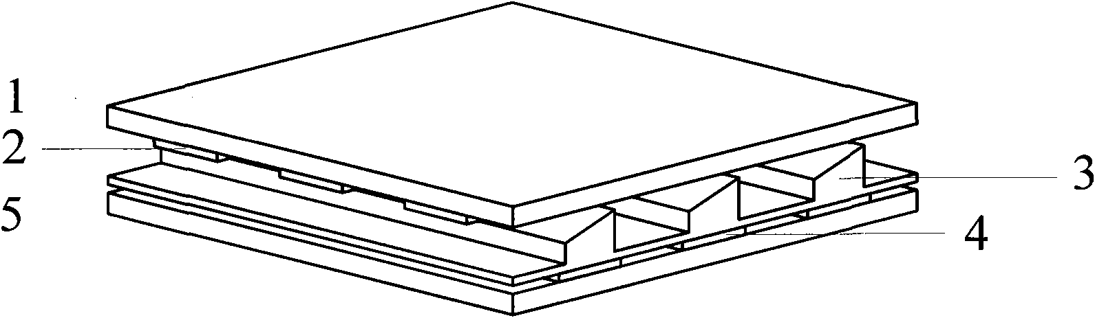
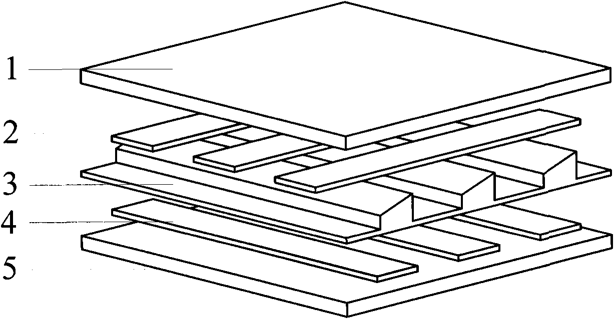
[0030] Such as figure 2 and image 3 , the array type flexible force-sensitive sensor that present embodiment 1 provides, it comprises:

[0031] The array type flexible force sensitive sensor provided by the present invention comprises:

[0032] An upper insulating protective layer 1 and parallel metal row electrodes 2 patterned on the lower surface of the upper insulating protective layer 1;

[0033] The lower insulating protective layer 5 and the parallel metal column electrodes 2 patterned on the upper surface of the lower insulating protective layer 5;

[0034] and

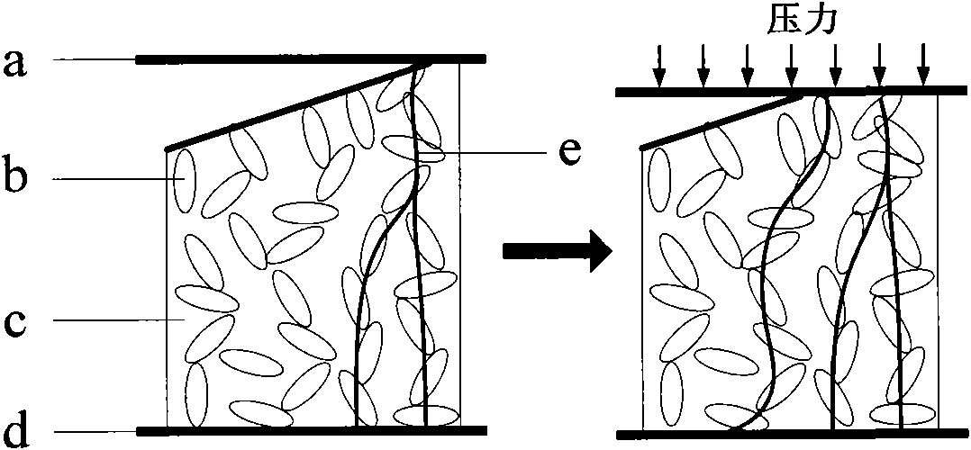
[0035] A first sensitive film layer 3 positioned between the parallel metal row electrodes and the parallel metal column electrodes; the first sensitive film layer 3 is composed of a filled sensitive material layer 31 and attached to the filled sensitive material layer 31 is composed of a filled sensitive material convex strip 32 or a filled sensitive material convex block 33 on the upper surface; the lon...

Embodiment 2

[0050] The difference between this embodiment and embodiment 1 is that: the first sensitive film layer 3 is prepared by compression molding. The first sensitive film layer 3 is a film layer made of a filled conductive composite material in which conductive particles b are uniformly dispersed in an insulating flexible base material c. The conductive particle b is selected from carbon black, the insulating flexible base material c is made of polysilicone rubber, and the mass ratio of the conductive particle b to the insulating flexible base material c is 15:100; the filled conductive composite material is prepared by a solution method.

[0051] The mold required for film molding is manufactured by machining or MEMS technology. Put the filled conductive composite material into a compression molding machine, heat to 200° C., wait for the material filled conductive composite material to melt, apply pressure to the compression molding machine, cool the material to room temperature, ...

Embodiment 3

[0053] The difference between this embodiment and Embodiments 1 and 2 is that the convex strips 32 of the first sensitive film layer 3 are convex strips with a tapered longitudinal section or convex strips with a zigzag longitudinal section. The conductive particle b is selected from carbon black, the insulating flexible base material c is selected from polysilicone rubber, and the mass ratio of the conductive particle b to the insulating flexible base material c is 0.1:100.


PUM

PropertyMeasurementUnit
thicknessaaaaaaaaaa
thicknessaaaaaaaaaa
thicknessaaaaaaaaaa

Abstract

The invention relates to an array type flexible force sensor, which comprises an upper insulation protecting layer, a parallel metal row electrode graphically arranged on the lower surface of the upper insulation protecting layer, a lower insulation protecting layer, a parallel metal column electrode graphically arranged on the upper surface of the lower insulation protecting layer, and a first sensitive membrane layer positioned between the row electrode and the column electrode, wherein the first sensitive membrane layer consists of a filling type sensitive material layer and a filling typesensitive material convex strip or convex block adhered onto the upper surface of the filling type sensitive material layer, and the longitudinal section of the convex strip or convex block is in a wedge, conical or serrated shape; the convex strip or convex block is vertically aligned with the column electrode, and the row electrode and the column electrode are distributed in a spatial vertical intersection way; a spatial vertical intersection part and the first sensitive membrane layer contained in the spatial vertical intersection part form a force sensing unit, and the filling type sensitive material is a conductive composite material that conductive particles are uniformly dispersed in a flexible insulation matrix material. The array type flexible force sensor has the advantages of high sensitivity, stable performances, long service life and the like.

Description

technical field [0001] The invention belongs to the technical field of micro-electromechanical systems (MEMS) and sensing, and in particular relates to an array type flexible force-sensitive sensor. Background technique [0002] Because of its good flexibility, the flexible sensor is not limited by the shape of the object to be measured, and can be attached to various regular or irregular surfaces to realize the sensing function. The flexible force sensor is mainly used in the measurement of extrusion force and shear force, and can be used as a tactile sensor. Common flexible force sensors include piezoresistive, capacitive and optical. [0003] Because of the advantages of good flexibility, large measurement range and effective measurement area, and relatively simple process, the use of pressure-sensitive conductive rubber to make piezoresistive flexible force-sensitive sensors has gradually become the mainstream design idea. According to the working principle, it is main...

Claims


Application Information

Patent Timeline
Patent Type & Authority Patents(China)
IPC IPC(8): G01L1/18
Inventor 叶雄英王志峰
Owner TSINGHUA UNIV
Why Eureka
Try Eureka