Hinge

A hinge and joint technology, applied in the field of hinges, can solve the problems of improper distribution of spring return force, neglect of consideration, insufficient product practicability, etc., and achieve the effect of improving service life and avoiding elastic fatigue.

Active Publication Date: 2013-11-06
吴枝祥
View PDF5 Cites 0 Cited by
  • Summary
  • Abstract
  • Description
  • Claims
  • Application Information

AI Technical Summary

Problems solved by technology

Although the above-mentioned existing hinges can realize silent closing, they do not consider that when the door panel is opened, the self-elastic force of the hinge will combine the weight of the door panel and the self-spring angle to generate a huge impact force, which will be transmitted to the joint between the hinge body and the furniture , which seriously affects the service life of the hinge and furniture; on the other hand, the existing hinge still has the problem of improper distribution of the spring return force, that is, the torsion angle in the closed state is the smallest, and the torsion angle in the opening process is the largest. It will make the spring very prone to elastic fatigue, causing the spring's restoring force to decrease rapidly, and even cause the spring body to break, so that the product has the defect of insufficient practicability

Method used


Image

  • Hinge
  • Hinge
  • Hinge

Examples


Embodiment Construction

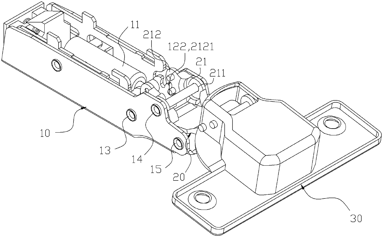
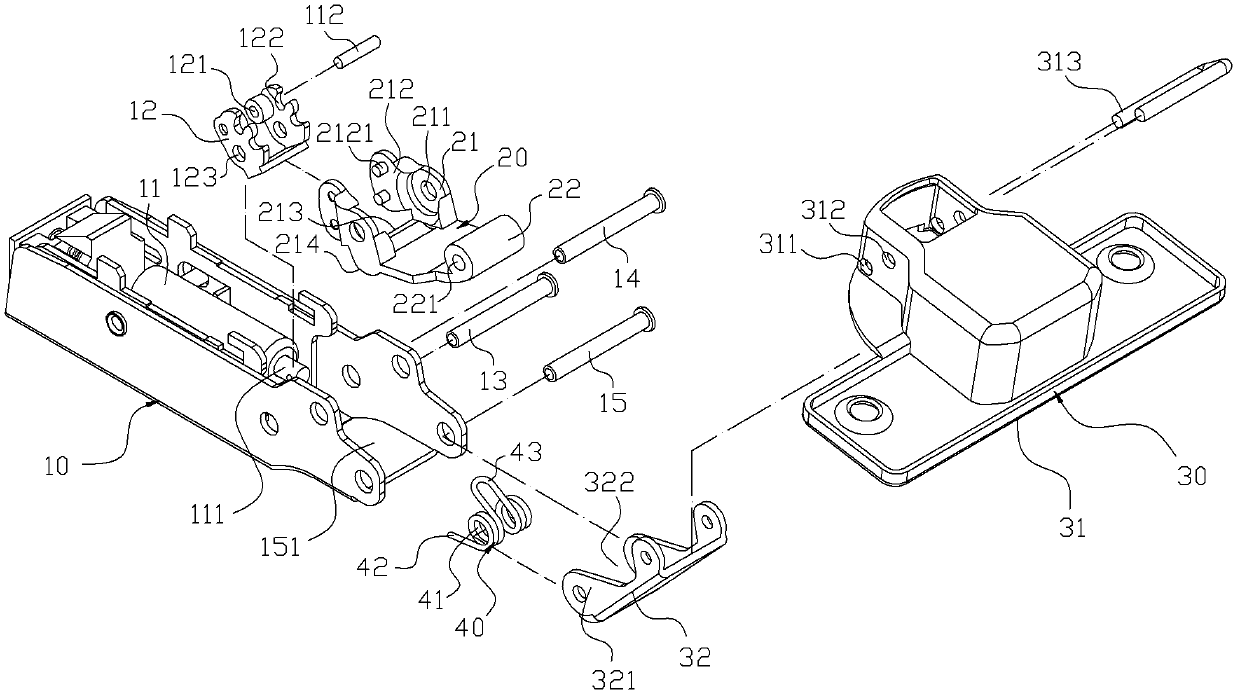
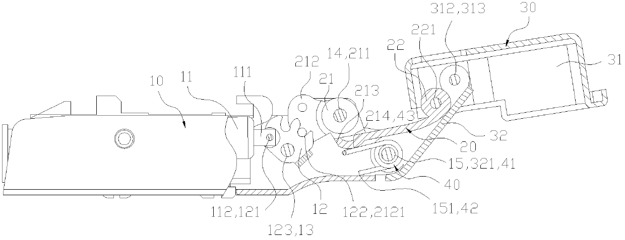
[0040] according to figure 1 and 2 As shown, the hinge of the present invention includes a hinge main body 10, a linking member 20, a movable seat 30 and an elastic member 40, wherein a buffer member 11 is hinged in the hinge main body 10, and the telescopic rod 111 of the buffer member 11 The front end is pierced with a shaft bolt 112, and the telescopic rod 111 is hinged with a swing block 12 through the shaft bolt 112; A first pivot hole 121 is set through the two connecting pieces. The telescopic rod 111 is placed between the two connecting pieces, and the pivot connection with the swing block 12 is realized through the cooperation of the shaft bolt 112 and the first pivot hole 121. The swing direction The block 12 is respectively provided with two snapping recessed arcs 122 on the upper edge of the two connecting pieces, and is provided with a second pivot hole 123 passing through the two connecting pieces at the other end; A first shaft 13, a second shaft 14, and a thi...


PUM


Abstract

The invention discloses a hinge. The hinge comprises a hinge main body, a coupling component, a movable seat and an elastic component, wherein the coupling component is connected with a swinging block in a meshing manner, and forms a coupling relation with a buffering component of the hinge main body; the coupling component is also in pivot connection with the movable seat through a pivot connection part at one end; a rocker arm is arranged on the position, adjacent to the movable seat, of the coupling component in a pivot manner; one end of the rocker arm is arranged on a third shaft rod of the hinge main body in a pivot manner; a connecting hole of the elastic component is used for the passing of the third shaft rod of the hinge main body; two supporting ends are formed by equi-directionally extending from both sides of the connecting hole; the supporting ends are against the bottom wall surface of the hinge main body; an against end, which is located at the same side as the supporting ends, is convexly extended from the middle of the elastic component; and the against end is against the bottom surface of the coupling component. Through the structure, the hinge can generate free travel route and buffering travel route with proper angles, thus the effects of reducing the impact force and noise while opening and closing door plates are achieved.

Description

technical field [0001] The present invention relates to a hinge structure, in particular to a hinge capable of generating a free stroke and a buffer stroke at an appropriate angle when the hinge body and the movable seat are opened and closed, so as to reduce the impact force and noise of opening and closing the door panel. Background technique [0002] In order to reduce the impact force and noise on the furniture body when the furniture door is closed, a damping device is usually installed between the furniture door and the furniture body to slow down the closing speed of the furniture door and reduce the impact force and noise of the door panel closing. Most of the existing hinges automatically switch to the pop-up state after the door panel is opened about 0° to 60°. When closing the door panel, the operator needs to apply a pressure greater than the self-elastic force of the hinge from the maximum opening angle of the door leaf to close the door panel to When it is abou...

Claims


Application Information

Patent Timeline
Patent Type & Authority Patents(China)
IPC IPC(8): E05F5/02E05F1/12
Inventor 吴枝祥
Owner 吴枝祥
Why Eureka
Try Eureka