
Assembly welding tooling for inner tube support plate of cryostat

A cryostat and support plate technology, applied in auxiliary devices, manufacturing tools, welding equipment, etc., can solve problems such as low work efficiency, difficult operation, deformation, etc., and achieve the effect of improving work efficiency and reducing labor intensity

Active Publication Date: 2015-04-22
无锡市创新低温环模设备科技有限公司
View PDF5 Cites 0 Cited by
  • Summary
  • Abstract
  • Description
  • Claims
  • Application Information

AI Technical Summary

Problems solved by technology

[0002] In the process of making the inner tube of the cryostat, because the length of the inner tube is relatively long and the tube wall is thin, for example, the number of support plates on the inner tube with a specification of φ312×6mm and a length of 11.45m is large, and the support plates are located at the same On the plane, the traditional method is to directly draw and draw lines on the inner tube with general measuring tools, and point and fix many support plates. It is difficult to ensure that the size and straightness of the support plates are within the allowable tolerance range, and when welding the support plates The inside of the tube must be filled with water. If the balance of the inner tube does not meet the requirements, some parts of the inner tube will not be filled with water. When welding the support plate, the part that cannot be filled with water will be deformed due to high heat. Therefore, it is difficult to control the deformation caused by welding when welding the support plate, resulting in low work efficiency and difficult operation

Method used


Image

  • Assembly welding tooling for inner tube support plate of cryostat
  • Assembly welding tooling for inner tube support plate of cryostat

Examples


Embodiment Construction

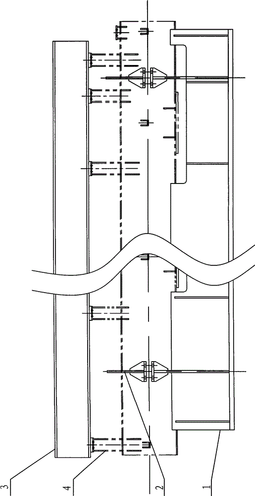
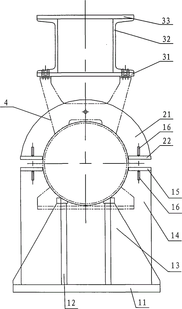
[0028] Such as figure 1 and 2 In the shown embodiment, the assembly and welding tooling of the inner tube support plate of the cryostat according to the present invention includes component I1, component II2 and component III3, component I1 and component II2 are connected by bolts, and component III3 is connected with the inner tube support plate 4 Bolt connection; assembly I1 includes a bottom plate 11 and a parallel reinforcing plate 12 welded thereon, a circular arc plate a14 whose radian is consistent with the outer diameter of the inner pipe, and the reinforcing plate 12 is arranged on the front and rear sides of the circular arc plate a14, and the reinforcing plate 12 Ribs 13 are welded on the left and right sides, support plates a15 are welded on the left and right sides of the upper end of the arc plate a14, and the two sides of the connection between the support plate a15 and the arc plate a14 are provided with reinforcing triangular plates 16; component II 2 includes...


PUM


Abstract

The invention discloses an assembly welding tooling for an inner tube support plate of a cryostat, which comprises an assembly I, an assembly II and an assembly III, wherein the assembly I comprises a base plate and a circular arc plate a arranged on the base plate; support plates a are respectively arranged at the left side and the right side of the upper end of the circular arc plate a; reinforcing plates are respectively welded at the front side and the rear side of the circular arc plate a; the assembly II comprises a circular arc plate b; support plates b are respectively arranged at two ends of the circular arc plate b; the assembly III comprises a steel plate a and a steel plate b; and the steel plate a and the steel plate b are welded into a whole through channel steels arranged between the steel plate a and the steel plate b. An inner tube is integrally arranged on the assembly I and is horizontally corrected; then the assembly II is connected with the assembly I by using a bolt; the integral roundness of the inner tube is controlled; the inner tube support plate is fixedly arranged on the assembly III by using bolts; the whole body is hung on the inner tube for welding by using hoisting equipment; and after a weld joint is completely cooled, various assemblies are detached. The precision of the size in the assembly process is ensured; and the tooling has a simple structure, convenience in operation as well as the advantages of improved work efficiency and reduced labor intensity.

Description

technical field [0001] The invention relates to a welding tool for accessories on a thin-walled tube, in particular to a welding tool for an inner tube support plate of a cryostat. Background technique [0002] In the process of making the inner tube of the cryostat, because the length of the inner tube is relatively long and the tube wall is thin, for example, the number of support plates on the inner tube with a specification of φ312×6mm and a length of 11.45m is large, and the support plates are located at the same On the plane, the traditional method is to directly draw and draw lines on the inner tube with general measuring tools, and point and fix many support plates. It is difficult to ensure that the size and straightness of the support plates are within the allowable tolerance range, and when welding the support plates The inside of the tube must be filled with water. If the balance of the inner tube does not meet the requirements, some parts of the inner tube will ...

Claims


Application Information

Patent Timeline
Patent Type & Authority Patents(China)
IPC IPC(8): B23K37/04
Inventor 张志洪
Owner 无锡市创新低温环模设备科技有限公司
Learn More