U-shaped switched reluctance motor

A switched reluctance and motor technology, applied in the field of motors, can solve problems such as steep price rise, demagnetization, reduction of motor power and efficiency, etc.

Inactive Publication Date: 2012-02-29
ZHEJIANG YIEN ELECTROMECHANICAL TECH
View PDF6 Cites 9 Cited by
  • Summary
  • Abstract
  • Description
  • Claims
  • Application Information

AI Technical Summary

Problems solved by technology

[0002] The current electric bicycles and electric motorcycles in my country all use permanent magnet brushless DC motors. This motor drive system has good control characteristics, but the disadvantages are: due to the use of permanent magnets, it is easy to demagnetize under high temperature and high current, thus The power and efficiency of the motor are gradually reduced; at the same time, since the main material of the permanent magnet is neodymium iron stilt, which is a strategic material, the current price has risen sharply

Method used


Image

  • U-shaped switched reluctance motor
  • U-shaped switched reluctance motor
  • U-shaped switched reluctance motor

Examples


Embodiment Construction

[0015] The present invention will be further described below in conjunction with the embodiments and accompanying drawings.

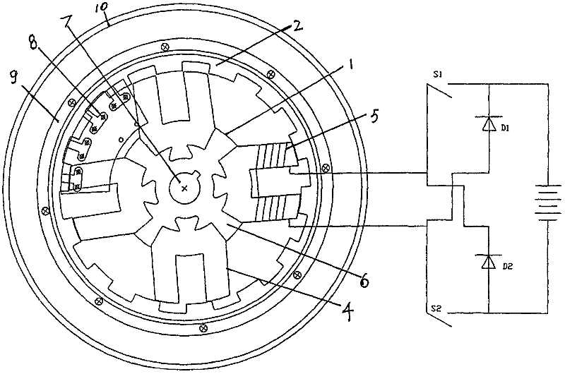
[0016] see Figure 1-Figure 8 , a U-shaped switched reluctance motor, which includes a stator 1, a rotor 2 and a side cover 3, the opposite salient poles in the stator are respectively provided with windings 5, the windings 5 ​​of radially adjacent poles are connected in series to form a phase, and the two windings 5 ​​each Connect switch S1, diode D2 and switch S2, diode D1 to connect the positive and negative poles of the power supply respectively. The stator 1 is composed of a magnetic spacer 6, a central shaft 7, a position plate 8 and a U-shaped salient pole 4. The central shaft 7 is embedded in the center of the magnetic spacer 6. , The position plate 8 is installed on the spacer magnet 6, four sets of U-shaped salient poles 4 are evenly embedded in the spacer magnet 6, and the U-shaped salient poles 4 have opposite salient poles.

[0017] see ...


PUM


Abstract

The invention discloses a U-shaped switched reluctance motor which comprises a stator, a rotor and a side cover, wherein windings are respectively arranged on opposite salient poles in the stator; the windings in radial opposite poles are connected in series to form a group; the two windings are respectively connected with a switch and a diode which are respectively connected with an anode and a cathode of a power supply; the stator comprises a shield magnet, a central shaft, position plates and U-shaped salient poles; the central shaft is embedded in the center of the shield magnet; the position plates are arranged on the shield magnet; four groups of U-shaped salient poles are uniformly embedded into the shield magnet; and the U-shaped salient poles are provided with opposite salient poles. The U-shaped switched reluctance motor has low start current, large torque and long endurance and is applied to an electric bicycle and an electric motorcycle.

Description

technical field [0001] The invention relates to a motor, in particular to a switched reluctance motor. Background technique [0002] The current electric bicycles and electric motorcycles in my country all use permanent magnet brushless DC motors. This motor drive system has good control characteristics, but the disadvantages are: due to the use of permanent magnets, it is easy to demagnetize under high temperature and high current, thus The power and efficiency of the motor are gradually reduced; at the same time, since the main material of the permanent magnet is neodymium iron stilt, which is a strategic material, the current price has risen sharply. The first inventor of this application once invented a "switched reluctance motor" (China, announcement number CN201577013U, announcement date September 8, 2010), which includes a stator and a rotor. The stator is a hollow columnar structure. The interior of the body is provided with multiple groups of salient poles arranged ...

Claims


Application Information

Patent Timeline
Patent Type & Authority Applications(China)
IPC IPC(8): H02K29/00H02K1/14H02K1/24
Inventor 樊新路连恩光廖流洲
Owner ZHEJIANG YIEN ELECTROMECHANICAL TECH
Why Eureka
Try Eureka