Small fingerprint acquirer
A fingerprint collector, small-scale technology, applied in the field of fingerprint identification devices, can solve the problems of inconvenient use, discomfort, and large distortion of fingerprint images collected by users in normal use, so as to improve the quality of collection and identification efficiency, and improve accuracy and clarity Accuracy, improving efficiency and accuracy
- Summary
- Abstract
- Description
- Claims
- Application Information
AI Technical Summary
Problems solved by technology
Method used
Image
Examples
specific Embodiment approach 1
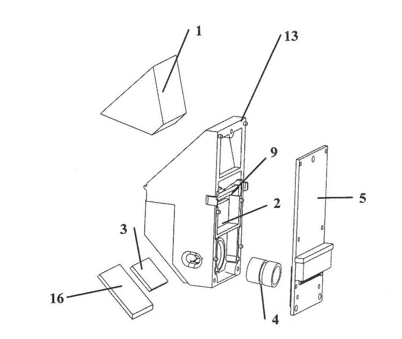
[0035] a kind of like Figure 1-8 The small-sized fingerprint collector shown in . The objective lens 4 and the image acquisition unit 5, the prism 1 is a uniform and symmetrical six-sided trapezoidal prism whose longitudinal section base is greater than the height, and includes a large end face 6, a small end face 7 parallel to each other, a lower side 8 and the remaining three sides, The large end surface 6 is the image acquisition surface, the small end surface 7 is the light source incident surface, and the lower side 8 is the imaging surface opposite to the imaging lens 2 .
[0036] The optical path between the imaging lens 2 and the imaging objective lens 4 is provided with a plane reflector 3, and the light emitted by the light source 9 enters the prism 1 through the small end face 7 of the prism 1, and is pressed on a part of the fingerprint reflected light on the large end face 6 of the prism 1, From the lower side 8 of the prism 1 to the imaging lens 2, the imaging ...
specific Embodiment approach 2
[0046] a kind of like Figure 1-7 , the small-sized fingerprint collector shown in 9,10, basically with specific embodiment one, difference is: image acquisition unit 6 is the image acquisition unit with USB communication interface, and it comprises CMOS photoelectric converter unit, DSP chip, and DSP chip The connected DSP crystal oscillator, storage unit EEROM, LDO, reset circuit, circuit for driving infrared emitting diode and illumination light source, infrared receiving diode receiving signal circuit and USB communication interface. The circuit for driving the emitting tube and the lighting source, and the receiving signal circuit for the receiving tube are respectively connected to the corresponding GPIO ports of the DSP chip. The DSP chip controls the infrared emitting diode 17 to emit light signals. When no finger presses the fingerprint collector, the infrared emitting diode 17 moves forward. The signal is emitted, the two visible light LED lighting sources are turned...
PUM
 Abstract
Description
Claims
Application Information
 - R&D
- Intellectual Property
- Life Sciences
- Materials
- Tech Scout
- Unparalleled Data Quality
- Higher Quality Content
- 60% Fewer Hallucinations
Browse by: Latest US Patents, China's latest patents, Technical Efficacy Thesaurus, Application Domain, Technology Topic, Popular Technical Reports.
© 2025 PatSnap. All rights reserved.Legal|Privacy policy|Modern Slavery Act Transparency Statement|Sitemap|About US| Contact US: help@patsnap.com


