
Electromagnetic band gap structure for optimizing power distribution network of PCB (printed circuit board) and construction method thereof

A technology of power distribution network and electromagnetic bandgap structure, which is applied in the direction of electrical components, printed circuits, printed circuit manufacturing, etc., can solve the problems of high relative frequency band bandwidth and low production cost.

Active Publication Date: 2012-02-22
BEIHANG UNIV
View PDF3 Cites 16 Cited by
  • Summary
  • Abstract
  • Description
  • Claims
  • Application Information

AI Technical Summary

Problems solved by technology

[0008] Since the noise in the power distribution network system of electronic circuits gradually extends to the frequency range of high frequency and ultra-high frequency, the current traditional addition of decoupling capacitors and the existing classic EBG structure cannot be well applied to such a high frequency range. And it is necessary to consider the manufacturing process and production cost of the electronic circuit. The present invention provides an electromagnetic bandgap structure and a construction method for optimizing the power distribution network of the PCB board. It realizes the characteristic requirements of high relative frequency bandwidth and low production cost.

Method used


Image

  • Electromagnetic band gap structure for optimizing power distribution network of PCB (printed circuit board) and construction method thereof
  • Electromagnetic band gap structure for optimizing power distribution network of PCB (printed circuit board) and construction method thereof
  • Electromagnetic band gap structure for optimizing power distribution network of PCB (printed circuit board) and construction method thereof

Examples


Embodiment Construction

[0055] The present invention will be further described in detail below in conjunction with the accompanying drawings.

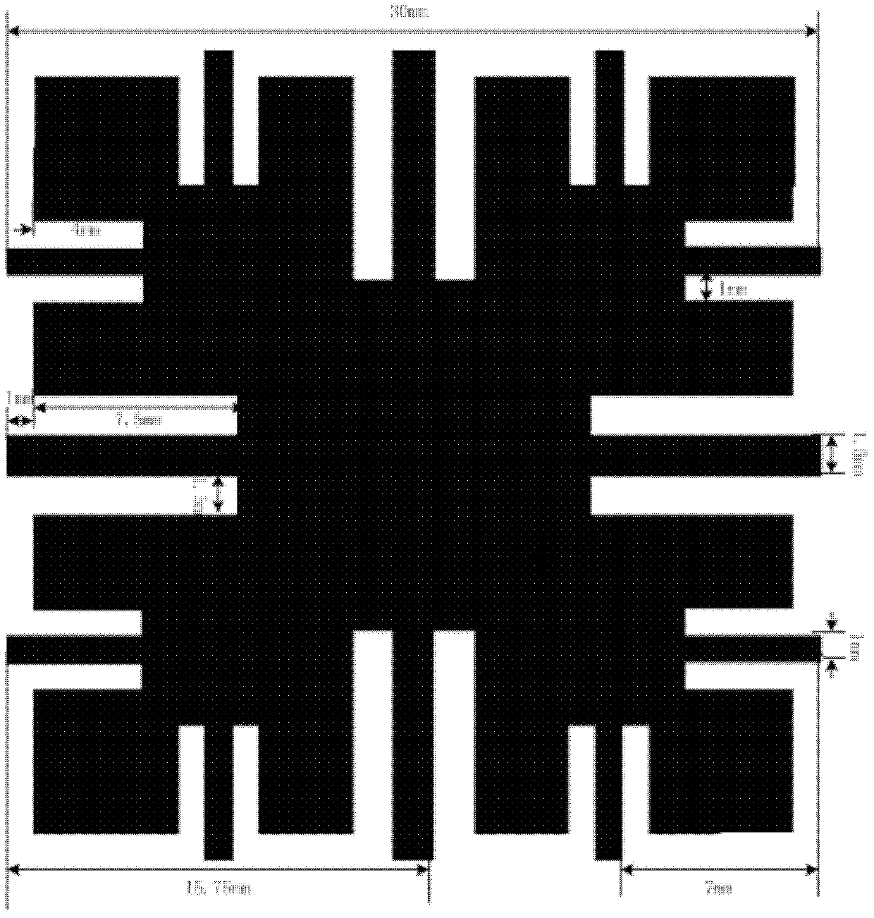
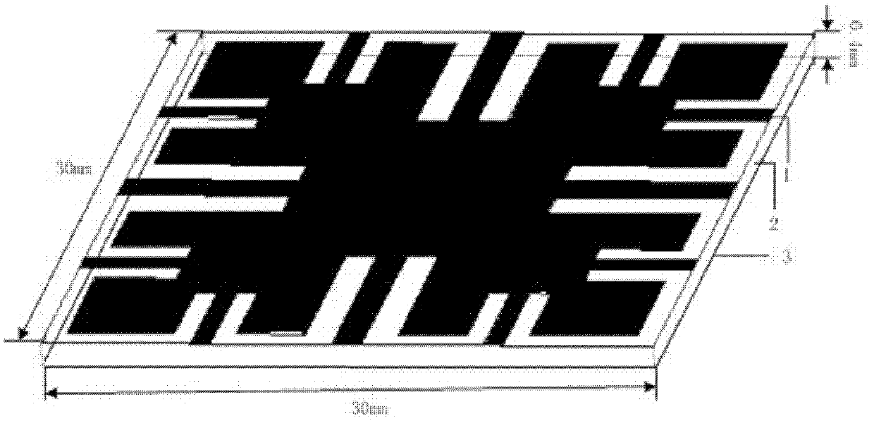
[0056] The invention designs a compound coplanar EBG structure with low lower limit cut-off frequency and high bandwidth for high-speed circuit system, which realizes suppression of high-frequency band noise in high-speed signal circuit PDN. On the basis of the traditional classic planar EBG structure, the structure increases the path of the narrow bridge-shaped connecting metal branches, makes full use of the redundant space of the structural unit, increases the spatial distribution rate of the narrow bridge-shaped connecting metal branches in the structural unit, and realizes the new EBG structure. The characteristics of low cut-off frequency and high bandwidth provide conditions for realizing the miniaturization of EBG structure. The composite coplanar EBG structure in the present invention is a 3×3 EBG structure formed by periodically extending a periodic...


PUM


Abstract

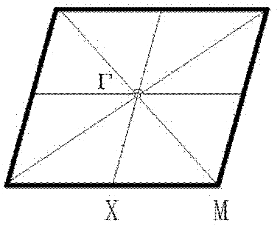
The invention discloses an electromagnetic band gap structure for optimizing a power distribution network of a PCB (printed circuit board), and the electromagnetic band gap structure is of a periodic structure. The shape of a periodic unit is formed by four large-size narrow-bridge-shaped connecting metal branches, eight small-size narrow-bridge-shaped connecting metal branches with same shapes, and square metal patches. All the periodic units are connected by utilizing the narrow-bridge-shaped connecting metal branches of all the edges. A construction method comprises the following seven main steps: (1) establishing a periodic structure unit layer of a zero-thickness composite coplanar EBG (Electromagnetic Band Gap) layer; (2) establishing a medium layer of the periodic structure units of the composite coplanar EBG layer; (3) establishing a dispersion diagram simulation model of the composite coplanar EBG periodic structure units; (4) carrying out periodic prolongation on the periodic structure units of the composite coplanar EBG layer obtained by the step (1) along the X and Y directions to obtain the composite coplanar EBG layer; (5) establishing a medium layer of an EGB structure and embedding the composite coplanar EBG structure layer into a substrate of a medium; (6) adding a simulation port to calculate an S parameter of the EBG structure; and (7) practically plating and testing the transmission characteristic of the composite coplanar EBG structure.

Description

(1) Technical field [0001] The invention relates to an electromagnetic bandgap structure for optimizing a power distribution network of a PCB board and a construction method thereof. The electromagnetic bandgap structure can suppress high-frequency and ultra-high-frequency power noise of a high-speed circuit power distribution network ("power distribution network" hereinafter referred to as PDN). It belongs to the field of high-speed circuit microwave technology. (2) Background technology [0002] With the advancement of semiconductor technology and the continuous emergence of new circuit technologies, circuit systems are developing towards the trend of high speed, high density, high power consumption, low voltage and high current. The reliability and stability of circuit system operation have become the key to the development of high-speed circuits, which poses a serious challenge to the design of power distribution networks and power integrity analysis of contemporary ele...

Claims


Application Information

Patent Timeline
IPC IPC(8): H05K1/02H05K3/00
Inventor 阎照文韩雅静车明明曹晋
Owner BEIHANG UNIV
Learn More