
Intrusion detecting and positioning method for distributed optical fiber fence

A distributed optical fiber and intrusion detection technology, which is applied in the direction of measuring devices, electromagnetic wave reradiation, radio wave measurement systems, etc., can solve the problems of large signal fluctuations in optical systems, high system false alarm rate and false alarm rate, and difficulty in intrusion detection And other issues

Inactive Publication Date: 2012-02-22
UNIV OF ELECTRONICS SCI & TECH OF CHINA
View PDF5 Cites 35 Cited by
  • Summary
  • Abstract
  • Description
  • Claims
  • Application Information

AI Technical Summary

Problems solved by technology

[0004] In view of the above-mentioned prior art, the technical problem to be solved by the present invention is to provide a method for intrusion detection and positioning of distributed fiber optic fences, which solves the problem that the existing intrusion monitoring system is sensitive to external environment interference due to its long monitoring distance and the monitoring signal noise Relatively low, and at the same time, the optical system is easily affected by factors such as ambient temperature and unstable, resulting in large fluctuations in the signal itself, difficulty in intrusion detection, and high false alarm and false alarm rates in the system

Method used

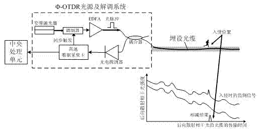
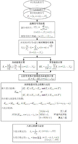
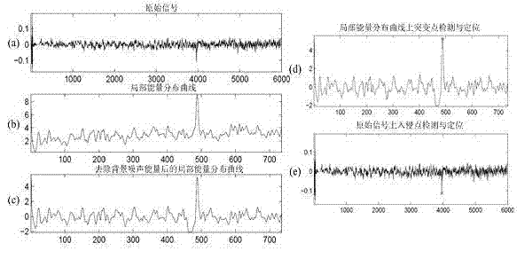

Image

  • Intrusion detecting and positioning method for distributed optical fiber fence
  • Intrusion detecting and positioning method for distributed optical fiber fence
  • Intrusion detecting and positioning method for distributed optical fiber fence

Examples


Embodiment Construction

[0047] The present invention will be further described below in conjunction with the accompanying drawings and specific embodiments.

[0048] see figure 1 , The Φ-OTDR distributed optical fiber fence system consists of three main parts, detection optical cable, light source and signal demodulation equipment, central processing unit, specific equipment and devices required from the system signal process include lasers that generate ultra-narrow coherent pulses And modulators, ordinary single-mode optical fibers buried near the perimeter or underground for sensing external intrusions, optical couplers, photodetectors for detecting optical signals, signal acquisition devices and central processing units; other amplification devices are based on monitoring distance requirements Selection, such as erbium-doped fiber amplifier, Raman amplifier, etc.; in the present invention, the strong coherent light emitted by the narrowband laser is modulated by the modulator to produce narrow p...


PUM


Abstract

The invention discloses an intrusion detecting and positioning method for a distributed optical fiber fence. The method comprises the following steps of: performing short-time Fourier transform on a monitoring signal to acquire instantaneous energy distribution of the monitoring signal along a laid optical cable; removing large-range background noise energy distributed along space; extracting information and a position of a mutation point which is relatively greatly changed and is locally abnormal from an energy sequence from which the background noise energy is removed; and judging whether the fence is actually intruded or not, and determining an intrusion position. In the method, mutation information at the mutation point is extracted by a short-time Fourier transform method, and the background noise energy is reduced while random noise is removed, so that the influences of interference to fluctuation noise caused by an unstable optical system and other factors are effectively eliminated, the problems of long-distance intrusion detection and positioning of the distributed optical fiber fence in a complicated application environment under a large noise background are solved, the accurate detection rate of an optical fiber fence intrusion monitoring system can be effectively improved, a false alarm rate can be reduced, and the confidence degree of a security alarming system during actual application can be improved.

Description

technical field [0001] The invention relates to the field of perimeter security and distributed optical fiber sensing signal processing, in particular to a phase sensitive optical time domain reflectometer (Φ-OTDR) type distributed optical fiber fence intrusion detection and positioning method. Background technique [0002] Phase sensitive optical time domain reflectometer (Φ-OTDR) is a new type of distributed optical fiber sensing technology. Same as the conventional optical time domain reflectometer (OTDR), the optical pulse is injected from one end of the optical fiber, and after being detected by the detector, it scatters light to Rayleigh to determine the disturbance and fault location. The difference is that the Φ-OTDR system injects strong coherent light, and what is detected is the result of the interference of backward Rayleigh scattered light within the pulse width range. The interference is judged by measuring the time delay between the input pulse and the receive...

Claims


Application Information

Patent Timeline
Patent Type & Authority Applications(China)
IPC IPC(8): G08B13/00G01S17/06
Inventor 吴慧娟李姗姗吴庥伟饶云江
Owner UNIV OF ELECTRONICS SCI & TECH OF CHINA
Learn More