
Infrared spectrum interferometer and infrared spectrometer employing interferometer

A technology of infrared spectroscopy and interferometer, applied in spectrometry/spectrophotometry/monochromator, interference spectroscopy, instruments, etc., can solve problems such as translation sensitivity, and achieve the effect of enhancing the ability to resist environmental interference

Active Publication Date: 2012-02-22
北京华夏谱创仪器有限公司
View PDF3 Cites 10 Cited by
  • Summary
  • Abstract
  • Description
  • Claims
  • Application Information

AI Technical Summary

Problems solved by technology

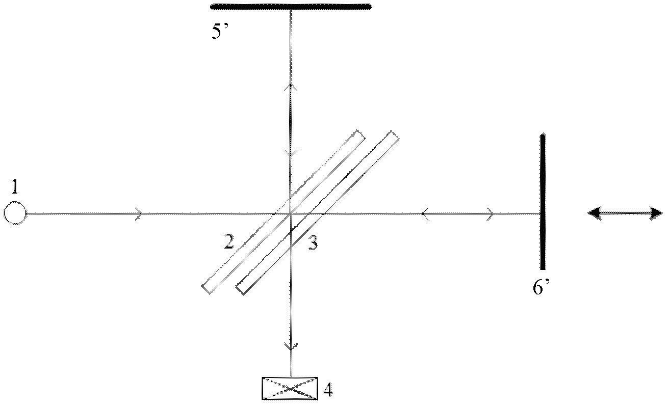
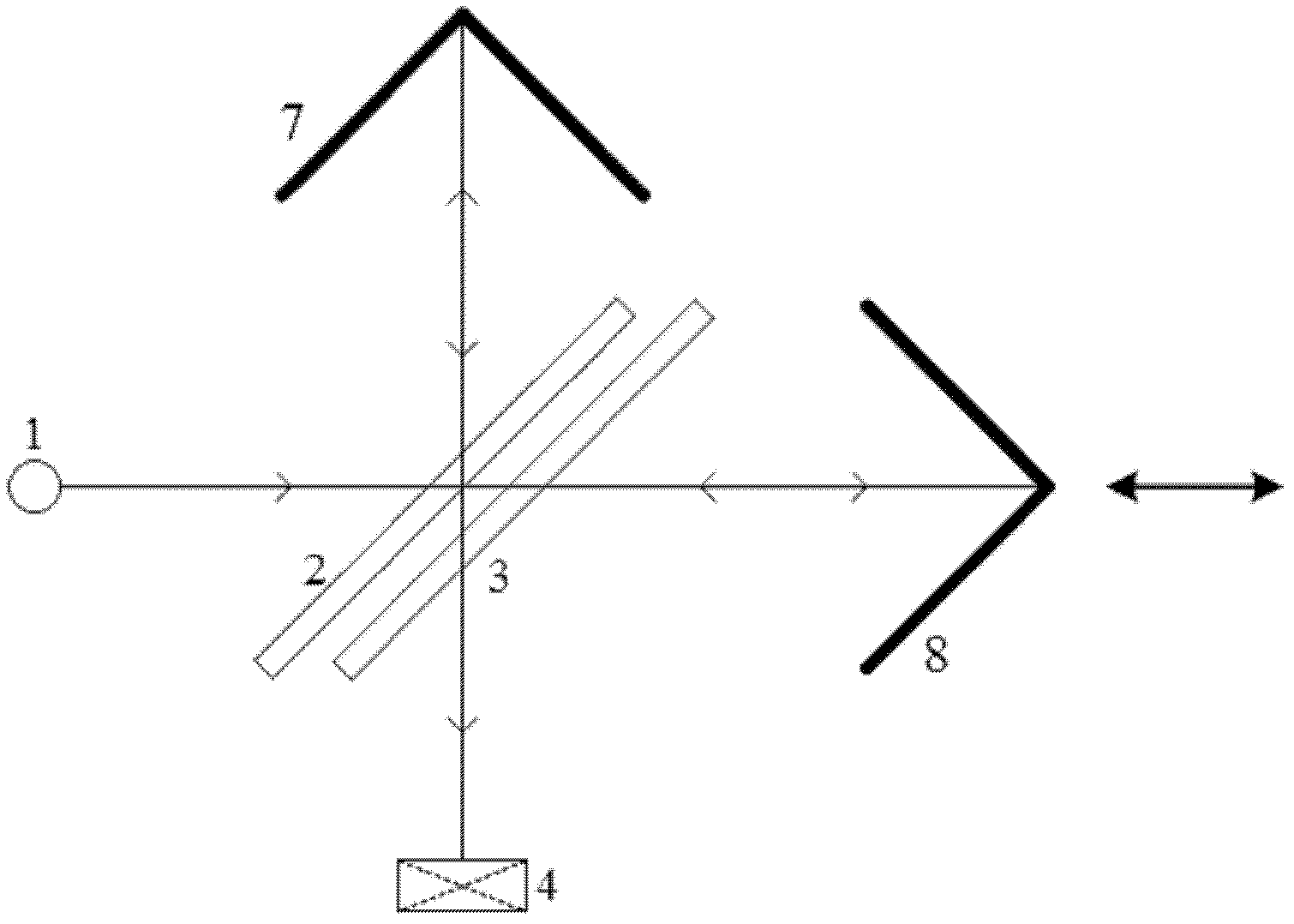
However, when the apex of the cube corner mirror 8 is translated back and forth (or up and down) along the direction perpendicular to the optical axis of the moving cube corner mirror 8, it will be found that the two paths of light will be reflected to different positions of the detector 4 after the movement
Therefore although the improved infrared spectrum interferometer is insensitive to the rotation of the dynamic cube corner mirror 8, it becomes sensitive to the forward and backward (or up and down) translation of the dynamic cube corner mirror 8 apex

Method used


Image

  • Infrared spectrum interferometer and infrared spectrometer employing interferometer
  • Infrared spectrum interferometer and infrared spectrometer employing interferometer
  • Infrared spectrum interferometer and infrared spectrometer employing interferometer

Examples


Embodiment 1

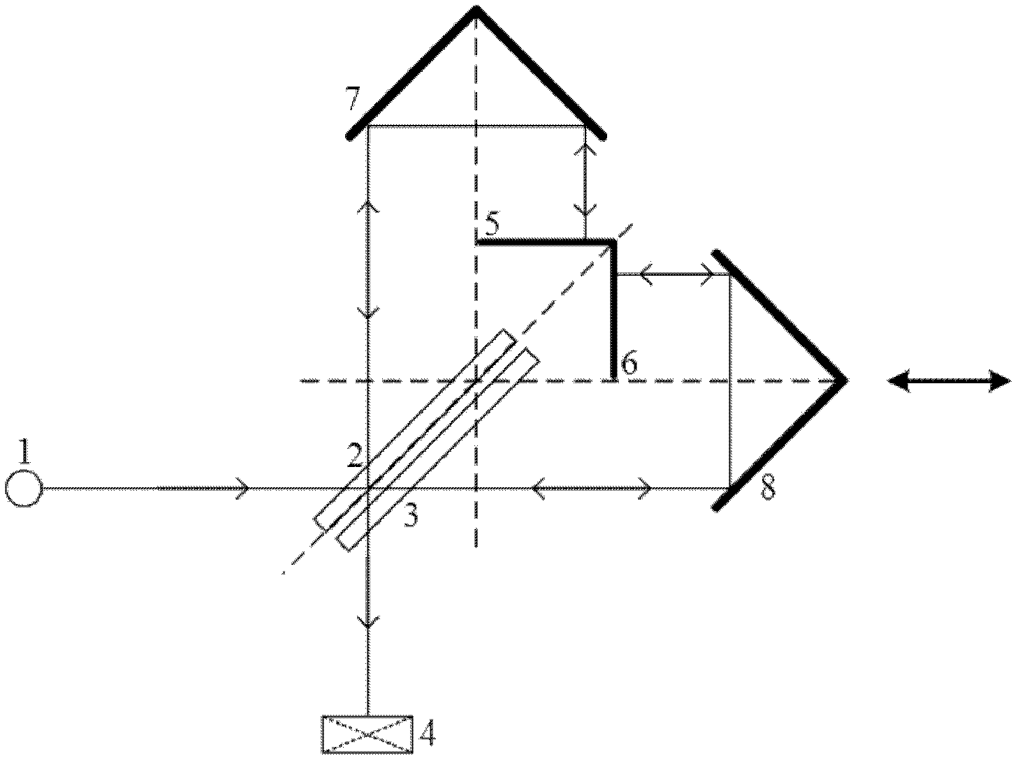
[0040] Such as image 3 Shown is a schematic diagram of an optical path of the infrared spectral interferometer of the present invention, and at the same time image 3 It can also be a schematic structural view of the infrared spectrum interferometer of the present invention, which includes a light source 1 capable of emitting parallel rays, a beam splitter 2 arranged at an angle of 135 degrees with the parallel rays, and sequentially on the transmission light path of the beam splitter 2 A compensating mirror 3, a moving cube corner 8 that can move left and right along its own optical axis direction, a fixed first flat mirror 6 that can reflect the light emitted by the moving cube corner 8 back along the original optical path, are arranged on the side of the beam splitter 2 A fixed fixed cube mirror 7 and a fixed second plane mirror 5 that can reflect back the emitted light of the fixed cube mirror 7 along the original optical path are sequentially arranged on the reflected li...

Embodiment 2

[0048] Figure 4 It is another optical path schematic diagram of the infrared spectrum interferometer of the present invention; at the same time Figure 4 It can also be another structural schematic diagram of the infrared spectrum interferometer of the present invention. The difference between this embodiment and Embodiment 1 is that the angle between the first plane mirror 6 and the second plane mirror 5 is 60 degrees, and at this time, the beam splitter 2 is set at an angle of 120 degrees to the incident parallel light. The optical axis of the fixed cube corner mirror 7 is perpendicular to the second plane mirror 5 and passes through the edge of the second plane mirror 5 , and the optical axis of the movable cube cube mirror 8 is perpendicular to the first plane mirror 6 and passes through the edge of the first plane mirror 6 .

[0049] The structure with an included angle of 60 degrees is conducive to the utilization of the beam splitter 2. It can be calculated that in th...

Embodiment 3

[0051] In the infrared spectrum interferometer in embodiment 1, the slight position change and angle offset of the moving cube-corner 8 and the fixed cube-corner 7 will not affect the degree of interference of the interferometer. Compared with the prior art, the infrared spectrum has been greatly improved. The stability of the spectral interferometer. However, the surface of the beam splitter 2 coated with the beam splitting film must be strictly parallel to the angle bisector of the angle between the second plane mirror 5 and the first plane mirror 6, and the error should generally be within 1-5 arc seconds, and the relative position change is very important. The influence of the degree of interference is still considerable. For this reason, this embodiment proposes an optical monomer structure, so that the relative positions of the first plane mirror 6, the second plane mirror 5 and the beam splitter mirror 2 are fixed, so that the infrared spectrum interferometer can comple...


PUM


Abstract

The invention provides an infrared spectrum interferometer. And the infrared spectrum interferometer includes a light source that emits a parallel light; a beam splitter prism is arranged at a heading direction of the parallel light; a compensating mirror, a movable solid angle mirror and a first plane mirror are successively arranged on a transmitted light path of the beam splitter prism; and a fixed solid angle mirror and a second plane mirror are successively arranged on a reflected light path of the beam splitter prism. Besides, a beam splitter prism plane, which is plated with a beam splitting coating, is in parallel with an angular bisector of an included angle that is formed by the second plane mirror and the first plane mirror; the second plane mirror is perpendicular to an optical axis of the fixed solid angle mirror; and the first plane mirror is perpendicular to an optical axis of the movable solid angle mirror. According to the infrared spectrum interferometer provided in the invention, the interferometer has a unique light path design; therefore, the interferometer is not only not influenced by angular deflection of solid angle mirrors but also not influenced by position translation of peaks of the solid angle mirrors, so that anti-environmental interference capability of the interferometer is strong. In addition, the invention also provides an infrared spectrometer that employs the infrared spectrum interferometer; and beneficially technical effects of the infrared spectrometer are the same as that of the infrared spectrum interferometer.

Description

technical field [0001] The invention belongs to the technical field of infrared spectrum measurement, in particular to an infrared spectrum interferometer and an infrared spectrometer using the infrared spectrum interferometer. Background technique [0002] Infrared spectroscopy is the fingerprint spectral region of substances. So far, a wealth of infrared spectral data has been accumulated, which provides a powerful means for identifying unknown compounds and quantitatively analyzing the content of compounds. Due to the small amount of light passing through the slit of the grating spectrometer, and the infrared radiation of the infrared light source is much weaker than that of the visible light, the grating spectrometer has gradually been eliminated in the infrared band. By the 1970s, based on the vigorous development of electronic computers, Fourier Transform Infrared Spectroscopy (FTIR) experimental technology entered the laboratory of modern scientists and became an impo...

Claims


Application Information

Patent Timeline
Patent Type & Authority Applications(China)
IPC IPC(8): G01J3/45G01J3/02
Inventor 曾立波张新民吴琼水
Owner 北京华夏谱创仪器有限公司
Learn More