
Truss combined beam and upper and layer connected light steel structure and construction method thereof

A light steel structure and composite beam technology, applied in truss-type structures, long-strip structural members for load-bearing, truss beams, etc., can solve the problems of low production efficiency, poor integrity of components, weak connections, etc. The effect of poor connection strength, high manufacturing precision and convenient connection

Inactive Publication Date: 2013-10-30
筑巢(北京)科技有限公司
View PDF6 Cites 0 Cited by
  • Summary
  • Abstract
  • Description
  • Claims
  • Application Information

AI Technical Summary

Problems solved by technology

[0007] The purpose of the present invention is to provide a light steel structure and its construction method in which the truss composite beam is connected to the upper and lower floors, and the connection between the floor beam and the upper and lower wall load-bearing trusses is not firm, and the local pressure of the floor beam is difficult to meet. The problem of stress requirements; it is also necessary to solve the problem that the floor beams, connecting pipes and floor slabs are prone to vibration and deformation; it is also necessary to solve the technical problems that the gusset plate is prone to damage first, the integrity of the components is poor, and the construction process is complicated; It is also necessary to solve the technical problems that the existing wall sheet columns are not firmly connected to the foundation, the form and structure of the column feet used for connection with the foundation are complicated, intensive production cannot be carried out, production efficiency is low, and on-site safety accidents are likely to be caused

Method used


Image

  • Truss combined beam and upper and layer connected light steel structure and construction method thereof
  • Truss combined beam and upper and layer connected light steel structure and construction method thereof
  • Truss combined beam and upper and layer connected light steel structure and construction method thereof

Examples


Embodiment Construction

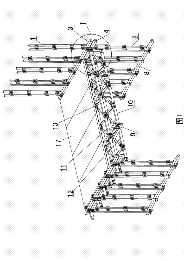
[0056] Examples see figure 1 , figure 2 As shown, this kind of light steel structure with truss composite beams connected to the upper and lower floors includes the upper wall sheet columns 1 distributed at intervals, the lower wall sheet columns 2 distributed at intervals, and the lower wall sheet columns connected between the upper wall sheet columns. The upper wall sheet column lower connecting pipe 3, the lower wall sheet column upper connecting pipe 4 connected between the top of the lower wall sheet column, and the upper wall sheet column and the lower wall sheet connected by the upper and lower layer connectors The truss composite beam between the columns, the upper wall sheet column 1 and the lower wall sheet column 2 both include two vertical rods and a vertical rod connector connected between the two vertical rods, and the truss composite beam includes Floor beams 10 distributed at intervals in the horizontal direction and connecting beams 9 connected between the f...


PUM


Abstract

A light-weight steel structure for connecting truss composite beam to upper and lower layers and a construction method therefor, comprising upper layer wall panel posts (1) distributed at intervals, lower layer wall panel posts (2) distributed at intervals, a lower connecting tube for the upper layer wall panel posts (3) connected between the lower parts of the upper layer wall panel posts (1), an upper connecting tube for the lower layer wall panel posts (4) connected between the upper parts of the lower layer wall panel posts (2), and a truss composite beam connected between the upper layer wall panel posts (1) and the lower layer wall panel posts (2) by means of an upper and lower layer connector, the upper and lower layer connector being a cross-beam fastening (5), wherein a cross-beam fastening web (5.1) is composed of an upper web (5.12) and a lower web (5.13); a square connecting part (5.8) is provided between the upper web (5.12) and the lower web (5.13); an upper chord connecting plate (5.9) extends from the left and right side edges of the square connecting part (5.8); and the upper chord connecting plate (5.9) and a cross-beam fastening side plate (5.2) are located in the same plane.

Description

technical field [0001] The invention relates to a light steel structure and a construction method thereof, in particular to a light steel structure used in a light steel keel system building and a construction method thereof. Background technique [0002] The light steel keel housing system has the advantages of light weight, good seismic performance, small wall thickness, good thermal insulation performance, low construction pollution, fast construction speed, no need for support boards, convenient pipeline layout, less residual waste, and can promote energy conservation and environmental protection , can be produced in a factory and can promote the development of the construction industry, so it has been widely used in the construction industry at home and abroad in recent years. [0003] In the current light steel keel building system, two methods are adopted for the wall load-bearing truss and truss composite beam: 1. The traditional C-shaped cold-formed thin-walled stee...

Claims


Application Information

Patent Timeline
Patent Type & Authority Patents(China)
IPC IPC(8): E04B1/19E04B1/58E04G21/14
CPCE04B2001/2415E04B1/24E04B1/58E04B2001/2451E04B1/19E04B2001/2472E04C2003/0491E04C3/08E04B2001/246E04G21/14E04B2001/2463
Inventor 丛玉臣
Owner 筑巢(北京)科技有限公司
Learn More