
Orbital parameter measurement device and method based on absolute coordinate measurement reference system

A technology for measuring reference frames and track parameters, applied in measuring devices, optical devices, railway vehicle shape measuring devices, etc., can solve the problems of low accuracy, low efficiency, and slow measurement speed of measurement results, and overcome slow measurement speed, The effect of improving the degree of automation and improving operation efficiency

Active Publication Date: 2012-02-22
ZHUZHOU TIMES ELECTRONICS TECH CO LTD +1
View PDF6 Cites 49 Cited by
  • Summary
  • Abstract
  • Description
  • Claims
  • Application Information

AI Technical Summary

Problems solved by technology

[0007] The purpose of the present invention is to provide a track parameter measurement device and method based on an absolute coordinate measurement reference system, which can overcome the technical problems of slow measurement speed, low efficiency, and low accuracy of measurement results in the prior art. , which effectively improves the measurement efficiency

Method used


Image

  • Orbital parameter measurement device and method based on absolute coordinate measurement reference system
  • Orbital parameter measurement device and method based on absolute coordinate measurement reference system
  • Orbital parameter measurement device and method based on absolute coordinate measurement reference system

Examples


Embodiment Construction

[0037] The following will clearly and completely describe the technical solutions in the embodiments of the present invention with reference to the accompanying drawings in the embodiments of the present invention. Obviously, the described embodiments are only part of the embodiments of the present invention, not all of them. Based on the embodiments of the present invention, all other embodiments obtained by persons of ordinary skill in the art without creative efforts fall within the protection scope of the present invention.

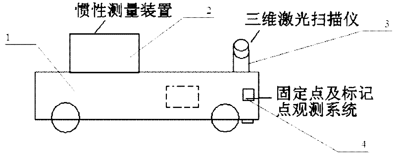
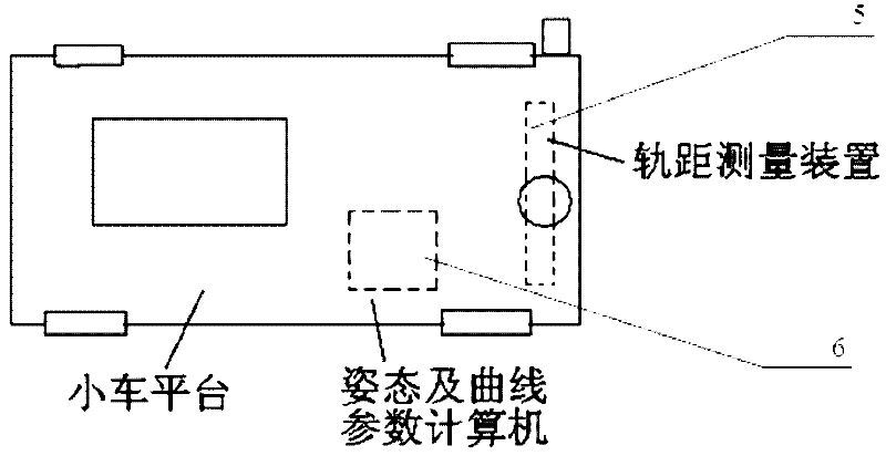
[0038] as attached figure 1 to attach Figure 5 As shown, a specific embodiment of a track parameter measurement device and method based on an absolute coordinate measurement reference system of the present invention applied to a railway locomotive track parameter measurement system is given. The present invention will be further described below in conjunction with the accompanying drawings and specific embodiments .

[0039] like figure 1 and figu...


PUM


Abstract

The invention discloses an orbital parameter measurement device and method based on an absolute coordinate measurement reference system. The orbital parameter measurement device comprises a trolley platform, an inertial measuring unit, a three-dimensional laser scanner, a fixed point and mark point observation system, a gauge measurement device and a gesture and curve parameter computer, wherein the trolley platform moves along a rail orbit and used for arrangement of required equipment; the inertial measuring unit is arranged on the trolley platform and used for measuring the corner motion amount and the acceleration change amount of the trolley in the spatial three-axis direction; the three-dimensional laser scanner is arranged on the trolley platform and used for measuring space position coordinate value of a reflector relative to the original point of the three-dimensional laser scanner; the fixed point and mark point observation system is used for positioning the initial space position of the trolley; the gauge measuring device is arranged on the trolley platform and used for measuring gauge parameters the rail at a current position where the trolley platform is located; and the gesture and curve parameter computer is used for calculating the curve parameters of the orbit according to the measured value. According to the orbital parameter measurement device and method disclosed by the invention, the technical problems of low measurement speed, low efficiency and low measured result precision can be solved, and the measuring efficiency is effectively improved on the promise of ensuring the measuring precision.

Description

technical field [0001] The invention relates to a track parameter measuring device and method thereof, in particular to a railway locomotive track parameter measuring device and method based on an absolute coordinate measurement reference system. Background technique [0002] Due to the influence of the train movement, the railway track will gradually shift and settle, and the static curve parameters of the track will gradually change with time. When the change range of the track curve parameters exceeds a certain allowable value, it will affect the train running It may even cause serious accidents such as derailment and overturning of the train. In order to accurately control the parameters of the track curve, it is necessary to accurately measure the curve shape of the track and the spatial coordinate value of the curve in the geodetic coordinates. However, due to the limited technical level , in practical engineering applications, it can better measure the shape of the tr...

Claims


Application Information

Patent Timeline
IPC IPC(8): B61K9/08G01B11/00
Inventor 伍启天季育文马世宏龚军
Owner ZHUZHOU TIMES ELECTRONICS TECH CO LTD
Learn More