
Hybrid oil-electricity energy-saving power device and control method thereof

A technology of power plant and motor controller, applied in power plant, pneumatic power plant, hybrid vehicle, etc., can solve the problems of weak hybrid power, difficult layout, high manufacturing cost, and achieve emission reduction, fuel saving, and emission improvement. Effect

Inactive Publication Date: 2012-02-22
甘联芳
View PDF7 Cites 5 Cited by
  • Summary
  • Abstract
  • Description
  • Claims
  • Application Information

AI Technical Summary

Problems solved by technology

[0005] The hybrid mode refers to the series and parallel mode. In this mode, only the electric motor is used to drive when starting and at low speed. When the speed increases, the engine and the electric motor share the power efficiently. This mode requires a power sharing device and a power generator. machine, etc., so the structure is more complicated
[0006] Most of the current hybrid systems are developed and applied by large automobile companies such as Europe, America and Japan. Common ones include the IMA parallel system of Honda Insight and the THS hybrid system of Toyota Prius. Among them, the IMA system of Honda Insight has a simple structure. However, the motor only has auxiliary functions and does not have pure electric driving capability, which belongs to the weak hybrid form; while the THS system of Toyota Prius has pure electric driving capability, but its power synthesis mechanism is complicated, large in size and high in manufacturing cost
[0007] Some hybrid systems, including internal combustion engine, motor, clutch, transmission, power battery, braking system and automatic control system of the whole vehicle, have the ability of pure electric driving, but there are too many assemblies, difficult layout, and vehicle failure. The power, fuel economy and emission performance are not satisfactory, and further improvement is needed

Method used


Image

  • Hybrid oil-electricity energy-saving power device and control method thereof
  • Hybrid oil-electricity energy-saving power device and control method thereof
  • Hybrid oil-electricity energy-saving power device and control method thereof

Examples


Embodiment 1

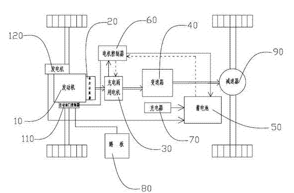
[0031] Such as figure 1 , the power unit is placed on a rear-wheel drive car, and the device includes a pedal 80, an engine 10, a gearbox 40 and a speed reducer 90, and also includes a charging dual-purpose motor 30, a motor controller 60, and a storage battery 50 and a power separator 20, the engine 10 is provided with an automatic throttle controller 110, and the engine is equipped with a generator 120, and a charger 70 can also be set to charge the storage battery 50, wherein the engine 10 is connected to charge through the power separator 20 The dual-purpose motor 30 and the charging dual-purpose motor 30 are connected to the reducer 90 through the gearbox 40. The reducer 90 is arranged on the shaft driven by the rear wheel of the automobile. The battery 50 provides power for the charging dual-purpose motor 30 through the motor controller 60. The motor 30, gearbox 40 and speed reducer 90 are used to form the driving system of the automobile in normal running state. When th...

Embodiment 2

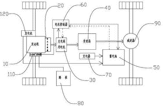
[0034] Such as figure 2 As shown, the power plant described in the application of the present invention can also be installed on a front-wheel-drive car, and its basic structure is the same as that of the first embodiment, and also includes a pedal 80, an engine 10, a gearbox 40 and a speed reducer 90, which also includes a dual-purpose charging motor 30, a motor controller 60, a storage battery 50, a charger 70 and a power separator 20, an automatic throttle controller 110 is provided on the engine 10, and the engine is equipped with a generator 120, each Part of the connection and control relationship is the same as that of the first embodiment, except that the speed reducer 90 is installed on the transmission shaft of the front wheel, and its working principle is the same as that of the first embodiment.

Embodiment 3

[0036] Taking Embodiment 1 as an example, the principle, working method and steps of using the described device to drive the vehicle with hybrid electric power are explained, and the described method is as follows:

[0037] 1. After ignition and during the smooth running of the car, the engine 10 is in the idling state, and the charged dual-purpose motor 30 alone provides power for the car. During driving, the engine 10 drives the attached generator 120 in the idling state To generate electricity, the generator 120 charges the storage battery 50 again, so as to achieve the purpose of not wasting the idle energy of the engine;

[0038] 2. During the deceleration and buffering of the vehicle, for example, the accelerator pedal 80 is released, and the automatic accelerator controller 110 transmits the change to the motor controller 60, and the motor controller 60 switches the charging dual-purpose motor 30 into the working state of the generator, giving Battery 50 reverse chargin...


PUM


Abstract

The invention provides a hybrid oil-electricity energy-saving power device which comprises a pedal, an engine, a gearbox, a speed reducer, a charge two-purpose motor, a motor controller, a storage battery and a power separator, wherein an automatic throttle controller is arranged on the engine, the engine is provided with a power generator, when the engine rotates at an idle speed, the charge two-purpose motor provides power for the running of a vehicle, meanwhile, the power generator carried by the engine can be used for charging the storage battery, when the vehicle runs through accelerating, the rotating speed of the engine is increased through the motor controller and the automatic throttle controller for carrying out oil-electricity hybrid power drive, when the vehicle slows down, the charge two-purpose motor can be used for carrying out reverse charge on the storage battery, and when electric quantity of the storage battery is insufficient, the engine singly provides power through a selector switch. The power system has excellent oil economy such that the running path is long after the vehicle is charged once, and accords with the trend of energy saving and environment friendliness.

Description

technical field [0001] The application of the present invention relates to a fuel-electric hybrid power device, in particular to a fuel-electric hybrid power device in a hybrid form with higher fuel economy and a control method thereof, belonging to the technical field of the automobile industry. Background technique [0002] Due to the environmental pollution and energy consumption of fuel-powered vehicles, electric vehicles and hybrid vehicles have become one of the hot spots in the development of the automotive field. The so-called hybrid generally refers to a hybrid of gasoline and electricity, that is, a mixture of fuel (gasoline, diesel) and electric energy. Common hybrid vehicles use electric motors as the auxiliary power of the engine to drive the vehicle. [0003] There are three types of power system structures for hybrid electric vehicles: series connection, parallel connection and hybrid connection. The so-called parallel mode is based on the engine as the main ...

Claims


Application Information

Patent Timeline
IPC IPC(8): B60K6/46B60W10/06B60W10/08B60W10/26B60W20/00B60W20/10
CPCY02T10/40Y02T10/62
Inventor 甘联芳
Owner 甘联芳
Learn More