Method for realizing federated filtering and timing synchronization in digital communication system
A digital communication system, timing synchronization technology, applied in multi-frequency code system, baseband system components, shaping network in transmitter/receiver, etc., can solve problems such as inability to reduce the number of parallel channels and high implementation complexity
- Summary
- Abstract
- Description
- Claims
- Application Information
AI Technical Summary
Problems solved by technology
Method used
Image
Examples
Embodiment 1
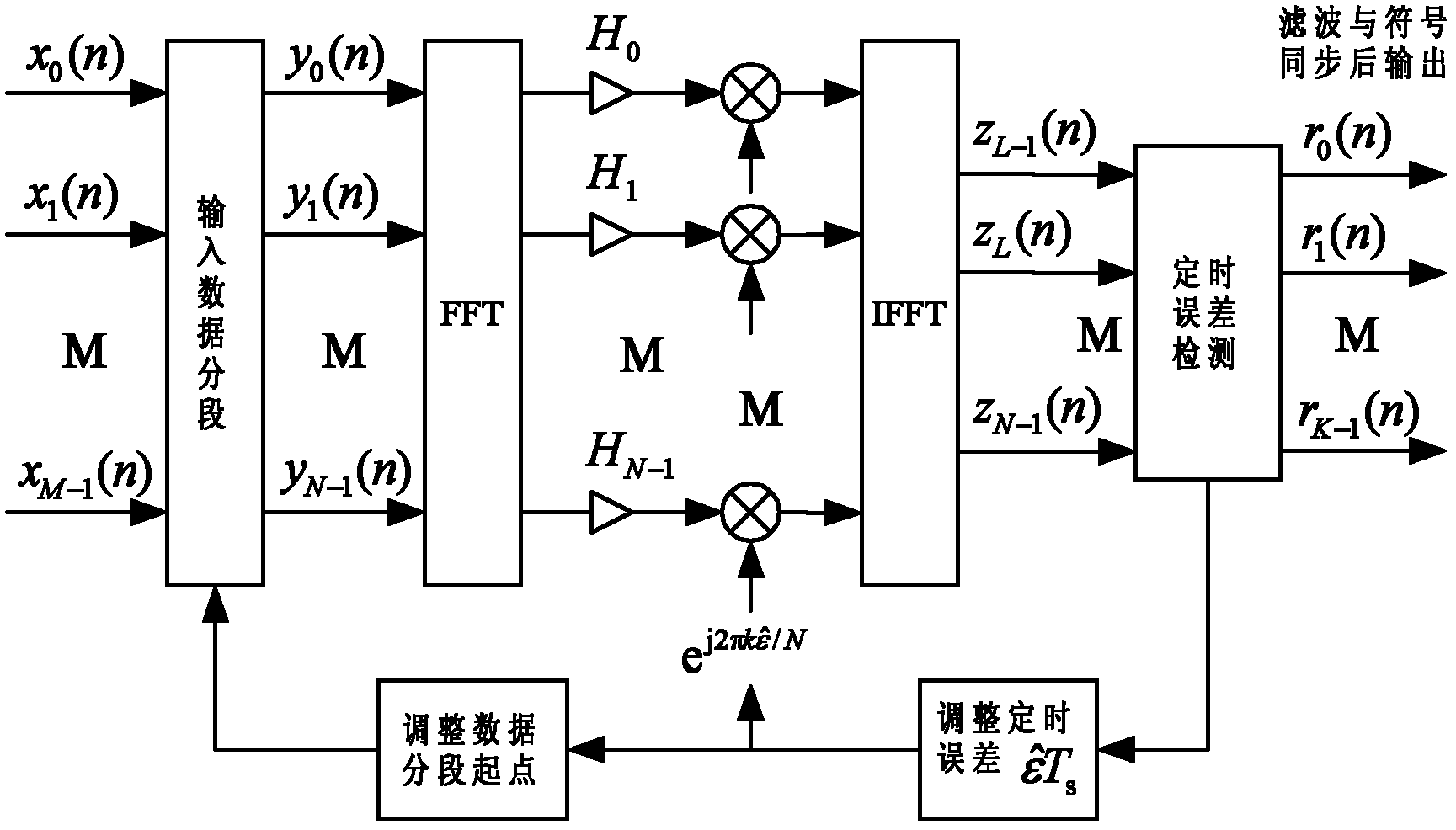
[0102] Assuming a QPSK modulation system, the symbol rate is f b =1 / T b =150MBaud, the receiver system adopts the analog quadrature down-conversion method, simultaneously samples the I and Q two-way signals in the baseband, the AD sampling rate is twice the symbol rate, and the sampling data is divided into M=2 parallel input digital demodulator, the processing clock frequency of the digital demodulator is f p =160MHz, the receiver matched filter adopts a root-raised cosine filter with a roll-off coefficient of 0.35, and the length of the filter coefficient is L=13. Then the structural diagram of the joint filtering and timing synchronization method is as follows: Figure 4 As shown, the implementation steps are as follows:
[0103] Step 1. Select the length of the FFT
[0104] Since the length of the filter coefficient is L=13, and the number of parallel paths of the input data is M=2, then the length N of the FFT is taken as an integer power of 2 not less than L+M-1=14, ...
Embodiment 2
[0123] Assuming a QPSK modulation system, the symbol rate is f b =1 / T b =405MBaud, the receiver system adopts the method of intermediate frequency direct sampling, and the intermediate frequency carrier frequency is f c =1.2GHz, the AD sampling rate is 4 times the symbol rate, namely f s =1.62Gsps, the sampling data is divided into M=16 parallel input digital demodulators, and the processing clock frequency of the digital demodulators is f p =110MHz, the receiver matched filter adopts a root-raised cosine filter with a roll-off coefficient of 0.35, and the length of the filter coefficient is L=25. Then the structural diagram of the joint filtering and timing synchronization method is as follows: Figure 6 As shown, the implementation steps are as follows:
[0124] Step 1. Select the length of the FFT
[0125] Since the length of the filter coefficient is L=25, and the number of parallel paths of the input data is M=16, then the length N of the FFT is taken as an integer p...
PUM
 Abstract
Description
Claims
Application Information
 - Generate Ideas
- Intellectual Property
- Life Sciences
- Materials
- Tech Scout
- Unparalleled Data Quality
- Higher Quality Content
- 60% Fewer Hallucinations
Browse by: Latest US Patents, China's latest patents, Technical Efficacy Thesaurus, Application Domain, Technology Topic, Popular Technical Reports.
© 2025 PatSnap. All rights reserved.Legal|Privacy policy|Modern Slavery Act Transparency Statement|Sitemap|About US| Contact US: help@patsnap.com


