
Multi-channel lowpass filter

A low-pass filter and low-pass filtering technology, applied in electrical components, impedance networks, etc., can solve the problems of unsatisfactory filtering accuracy and stability, steep transition band, poor phase-frequency characteristics, etc., to achieve high stability, Low temperature drift coefficient, the effect of overcoming amplitude fluctuation

Active Publication Date: 2012-02-15
NINGBO SHANGONG CENT OF STRUCTURAL MONITORING &CONTROL ENG
View PDF5 Cites 2 Cited by
  • Summary
  • Abstract
  • Description
  • Claims
  • Application Information

AI Technical Summary

Problems solved by technology

[0002] Multi-channel low-pass filters can transmit useful frequency components in the input signal, attenuate or suppress useless frequency components; traditional multi-channel low-pass filters mainly include Butterworth filters, Chebyshev filters and elliptic filters , the three have different passband and transition band characteristics; the elliptic filter has a steeper transition band and poorer phase-frequency characteristics than the Butterworth filter; the Chebyshev filter has a The transition band is narrow, and the phase-frequency characteristics are also poor; with the improvement of signal filtering requirements in the fields of safety production and monitoring and detection, the cut-off frequency of traditional multi-channel low-pass filters is relatively high, and its filtering accuracy and stability have been improved. It is increasingly unable to meet the requirements; while the Butterworth low-pass filter has good frequency response characteristics in the passband, and is used in bridges, dams, high-rise buildings, tunnels, highways, electric power, petrochemical, fire protection and HVAC, etc. The field of safety production and monitoring and testing has been rapidly developed and widely used

Method used


Image

  • Multi-channel lowpass filter
  • Multi-channel lowpass filter
  • Multi-channel lowpass filter

Examples


Embodiment Construction

[0023] The present invention will be further described in detail below in conjunction with the accompanying drawings and embodiments.

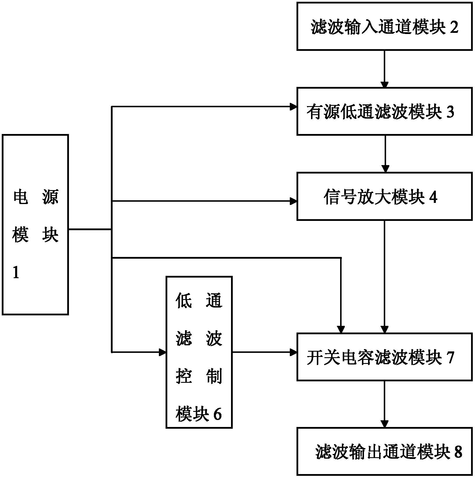
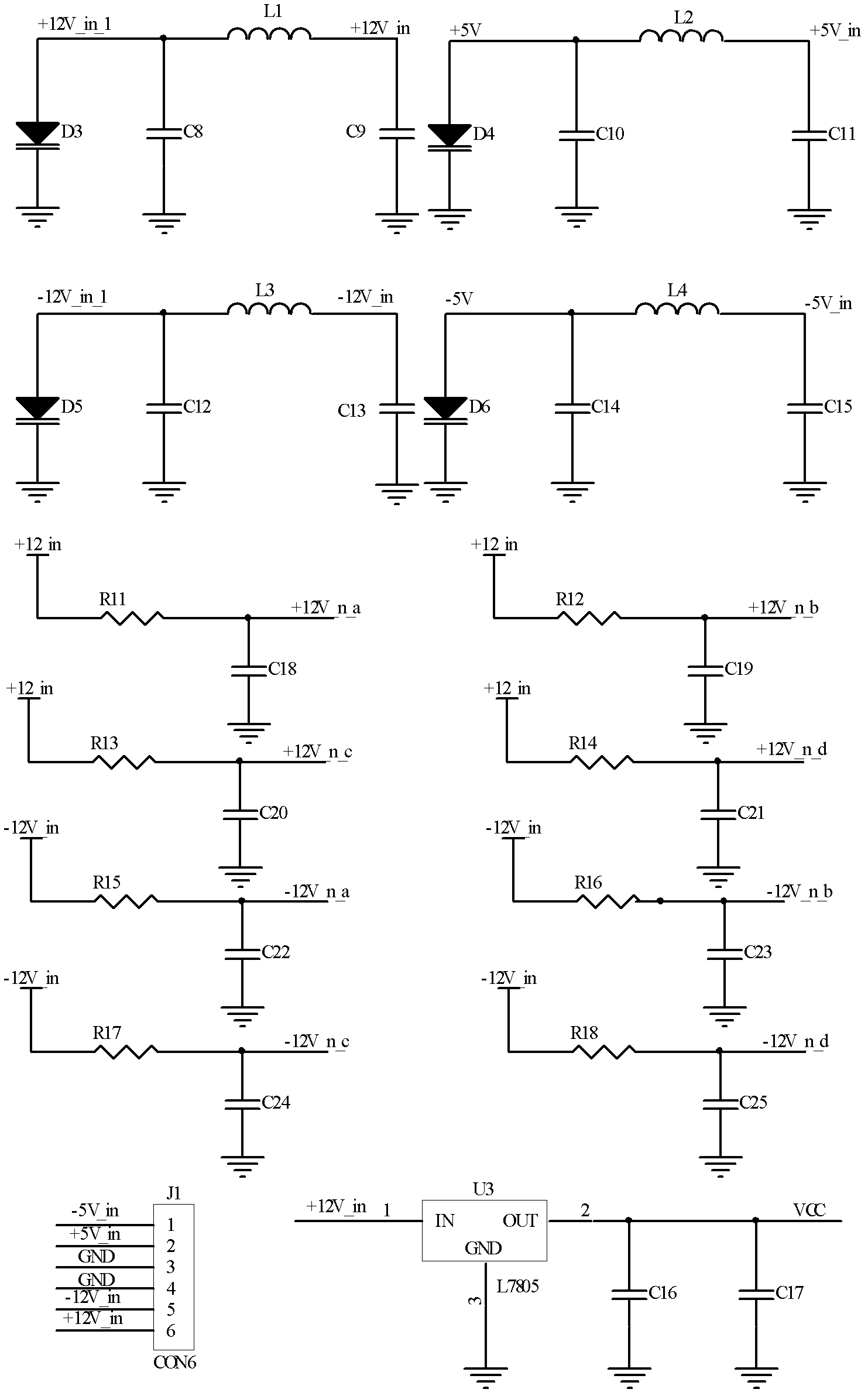
[0024] Such as figure 1 As shown, a multi-channel low-pass filter includes a power supply module 1, a low-pass filter control module 6 and at least one filter module, and the filter module includes a filter input channel module 2, an active low-pass filter module 3, and a signal amplification module 4 , the switched capacitor filter module 7 and the filter output channel module 8, the power supply module 1 is respectively connected with the low-pass filter control module 6, the active low-pass filter module 3, the signal amplification module 4 and the switched capacitor filter module 7, and the filter input channel module 2 The signal output end of the active low-pass filter module 3 is connected to the signal input end of the active low-pass filter module 3, the signal output end of the active low-pass filter module 3 is connected to the sign...


PUM


Abstract

The invention discloses a multi-channel lowpass filter, which comprises a power supply module, a lowpass filtering control module and at least one path of filtering module, wherein the filtering module comprises a filtering input channel module, an active lowpass filtering module, a signal amplification module, a switch capacitor filtering module and a filtering output channel module; the power supply module is respectively connected with the lowpass filtering control module, the active lowpass filtering module, a signal amplification module and a switch capacitor filtering module; the filtering input channel module is connected with the active lowpass filtering module; the active lowpass filtering module is connected with the signal amplification module; the signal amplification module is connected with the switch capacitor filtering module; the lowpass filtering control module is connected with the switch capacitor filtering module; and the switch capacitor filtering module is connected with the lowpass output channel module. The multi-channel lowpass filter has the advantages of large noise margin, strong anti-jamming capability, high precision, low cutoff frequency, small amplitude fluctuation during frequency response and high stability.

Description

technical field [0001] The invention relates to a low-pass filter, in particular to a multi-channel low-pass filter. Background technique [0002] Multi-channel low-pass filters can transmit useful frequency components in the input signal, attenuate or suppress useless frequency components; traditional multi-channel low-pass filters mainly include Butterworth filters, Chebyshev filters and elliptic filters , the three have different passband and transition band characteristics; the elliptic filter has a steeper transition band and poorer phase-frequency characteristics than the Butterworth filter; the Chebyshev filter has a The transition band is narrow, and the phase-frequency characteristics are also poor; with the improvement of signal filtering requirements in the fields of safety production and monitoring and detection, the cut-off frequency of traditional multi-channel low-pass filters is relatively high, and its filtering accuracy and stability have been improved. It...

Claims


Application Information

Patent Timeline
Patent Type & Authority Applications(China)
IPC IPC(8): H03H9/56
Inventor 李宏伟冷志鹏梁晓斌
Owner NINGBO SHANGONG CENT OF STRUCTURAL MONITORING &CONTROL ENG
Learn More