
Cavity machining track planning method based on numerical control operation system

A trajectory planning and operating system technology, applied in general control systems, control/adjustment systems, program control, etc., can solve the problems of inconsistency in surface quality and roughness of groove and cavity machining, and ensure the machining surface quality, high efficiency and flexibility. processing effect

Active Publication Date: 2012-02-15
HARBIN TURBINE +1
View PDF4 Cites 8 Cited by
  • Summary
  • Abstract
  • Description
  • Claims
  • Application Information

AI Technical Summary

Problems solved by technology

[0004] In order to solve the problem of inconsistent processing surface quality and roughness of the groove and cavity in the processing of the groove by the existing processing method, the present invention further provides a method for planning the groove processing trajectory based on the numerical control operating system; the method can be It is an efficient and flexible method for planning groove machining trajectory by directly machining the rounded groove on the opposite side of the CNC operating system.

Method used


Image

  • Cavity machining track planning method based on numerical control operation system
  • Cavity machining track planning method based on numerical control operation system
  • Cavity machining track planning method based on numerical control operation system

Examples


specific Embodiment approach 1

[0031] Specific implementation one: as Figures 1 to 10 As shown, the groove machining trajectory planning method based on the numerical control operating system described in this embodiment is implemented according to the following steps:

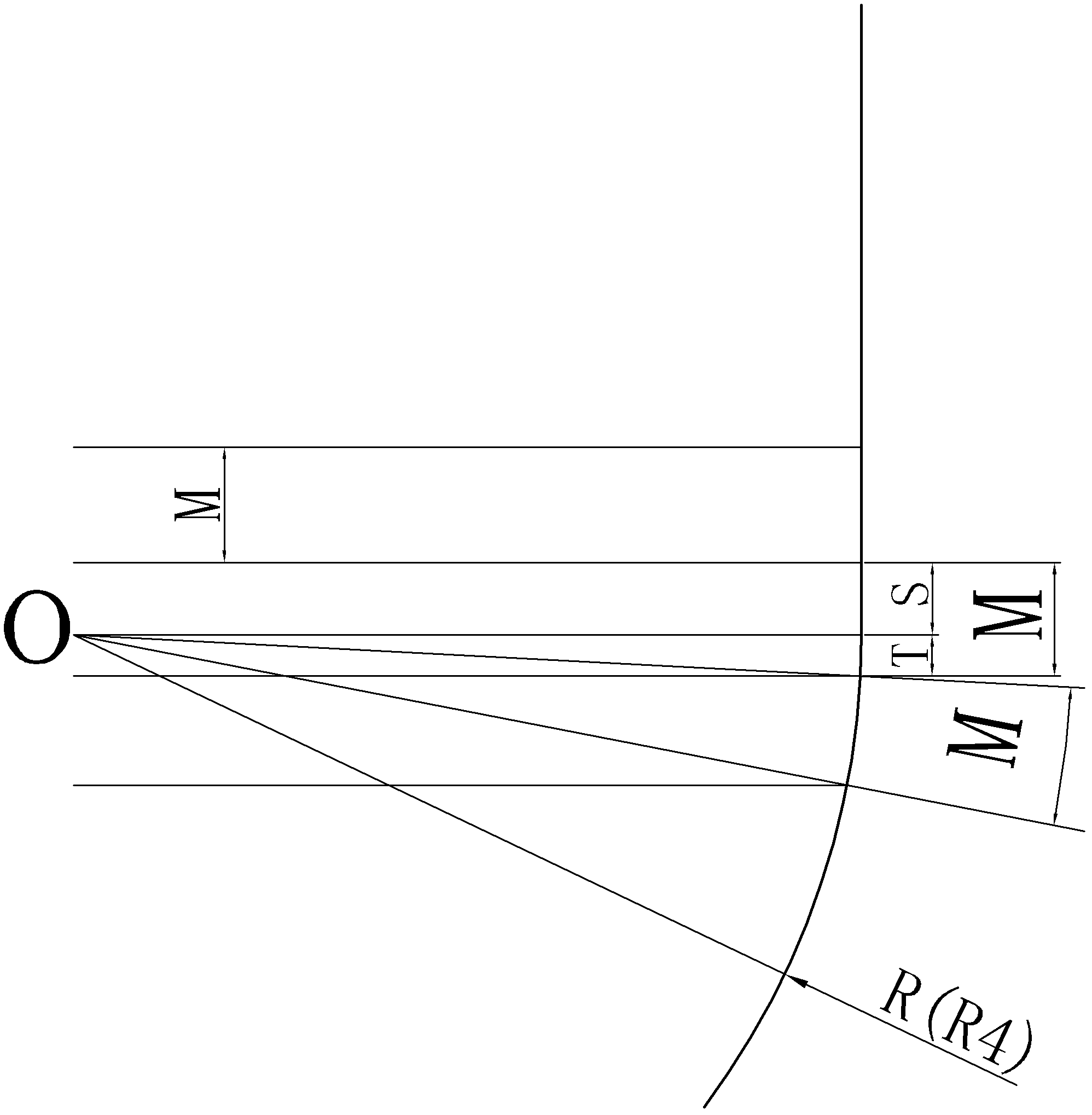
[0032] Step A. Based on the longitudinal section depth direction boundary trajectory of the groove on the drawing, the longitudinal section diagram combined line segment composed of straight lines and circular arcs is used to calculate the number of machining paths n (parameter R in the program) of the tool in the depth direction. 7 ) as the set condition variable to plan a set of uniformly arranged point sets projected on the combined line segment of the longitudinal section diagram, the distance between each adjacent two points is the step of the projection of the distance between the two adjacent trajectories on the combined line segment of the longitudinal section diagram. The long value M, and then control the uniform arrangement of t...

specific Embodiment approach 2

[0058] Specific implementation two: see image 3 , the groove machining trajectory planning method based on the numerical control operating system described in this embodiment further includes step B: calculating the groove side fixed cutting edge of the tool on the basis of selecting a suitable tool according to the trajectory planned in step A (1 ), the compensation value of the dynamic cutting edge (2) of the groove fillet surface and the tool setting point (O) of the tool to describe the trajectory of the tool setting point; the suitable tool means that the fillet of the tool is smaller than the groove to be machined the corner radius R. Other steps are the same as in the first embodiment.

[0059] Tool selection: Because the side wall of the groove is straight, and the bottom edge is rounded, it is more appropriate to use a rounded end mill, which can not only improve the processing efficiency of the side wall, but also meet the surface quality of the rounded face. , so...

specific Embodiment approach 3

[0060] Specific implementation three: as Figures 1 to 5 and Image 6 As shown, this embodiment is a specific process of programming using the method of the present invention:

[0061] Step 1. Planning method for evenly arranging the trajectory of the edge rounded groove:

[0062] Based on the known dimensions of the groove on the drawing (see Figure 4 ) Considering that the longitudinal section boundary trajectory of the groove is a combination curve of a straight line and a circular arc process, through a series of calculation methods, according to the number of machining trajectories n (parameter R in the program) in the depth direction of the tool 7 ) setting to plan a set of evenly arranged point sets projected on the combined line of the longitudinal section, and then control the projection of the cutting path of the tool to be evenly arranged on the inner surface of the groove (see Image 6 ).

[0063] Step 2: Calculate the compensation value of the cutting point a...


PUM


Abstract

The invention discloses a cavity machining track planning method based on a numerical control operation system, relates to a cavity machining track planning method, and aims to solve the problem of surface quality and roughness inconsistence in machining a diccavity of the cavity by using the traditional machining method. The cavity machining track planning method based on the numerical control operation system has the key technical points as follows: a machining track number of times n is used as a set condition variable, a track distance step value can be changed through changing the machining track number of times n by only deducing an overall length formula of combined line segments; the overall length of the combined line segments is equal to the sum of the length of a straight line segment and an arc segment, a step value of a projection of a track distance on the combined line segments can be solved through dividing a set track number by the overall length of the combined line segments, the projection distance of the track distance on the straight line segment part is the solved step value, and the distance projection between two tracks at a combined part of the straight line segment and the arc segment in the combined line segments is composed of a small segment of straight line segment and a small segment of arc segment together, so that a length formula of the small segment of straight line segment and the small segment of arc segment is deduced. By using the method provided by the invention, the precision for precision machining of the slotting of an edge-chamfering cavity is consistent.

Description

technical field [0001] The invention relates to a method for planning a machining trajectory of a profile groove, in particular to a method for planning a machining trajectory of a profile groove side wall and bottom edge fillet under a numerical control operating system. Background technique [0002] In the past, the groove edge of the part was rounded to form a fillet surface. In the three-axis machining process, a convex semicircular cutter (or ball cutter) with the same radius as the fillet surface was usually used. With the rapid development of processing fields such as molds and CNC technology, it is usually It is to use PROE, UG and other software to draw graphic modeling, and then use the CAM function of these software to post-process the graphic modeling to automatically generate a program, and input the program into the machine tool to complete the processing. However, due to the limitations of the software processing environment, for three-axis pocket milling, onl...

Claims


Application Information

Patent Timeline
Patent Type & Authority Applications(China)
IPC IPC(8): G05B19/402
Inventor 高岩杨东波孙智勇王龙梅宋兵史云鹏乔义明李强王治军王时光
Owner HARBIN TURBINE
Learn More