
Straight-through type double-support ultra-fine ring roller grinder

A double-support, ring roller milling technology, applied in grain processing, etc., can solve the problems of large mechanical loss, low grinding efficiency, and large vibration of the milling host, so as to reduce mechanical collision and wear, improve grinding efficiency, and improve overall rigidity Effect

Inactive Publication Date: 2012-02-15
GUILIN SHENGXING MACHINERY MFG
View PDF9 Cites 14 Cited by
  • Summary
  • Abstract
  • Description
  • Claims
  • Application Information

AI Technical Summary

Problems solved by technology

[0005] The negative pressure air port of the system (communicated with the atmosphere) is set at the bottom of the main mill to form an open structure. This open structure restricts the production capacity of the ultra-fine ring roller mill. Due to the need to match the negative pressure pumping capacity of the system, the feeding of materials The amount should not be too large, if the amount of material put in is too large, the powder that cannot be pumped in time will flow out from the bottom of the milling machine to cause waste, and because too much material cannot be put in, the material layer between the ring roller and the grinding ring will be thin, resulting in The main machine of the mill has large vibration, high noise, low grinding efficiency, small output, and large mechanical loss
[0006] Furthermore, due to the upper structure of the classifier, the roller stand of the ring roller mill can only adopt a single support structure, that is, the main shaft support of the roller stand (at the lower part of the main shaft) is only the bearing position on the base of the main mill. , so the rotation stability of the grinding roller frame is not enough, which is also an important reason for the large vibration and high noise of the grinding machine

Method used


Image

  • Straight-through type double-support ultra-fine ring roller grinder
  • Straight-through type double-support ultra-fine ring roller grinder

Examples


Embodiment Construction

[0020] Below in conjunction with accompanying drawing, technical scheme of the present invention will be further described:

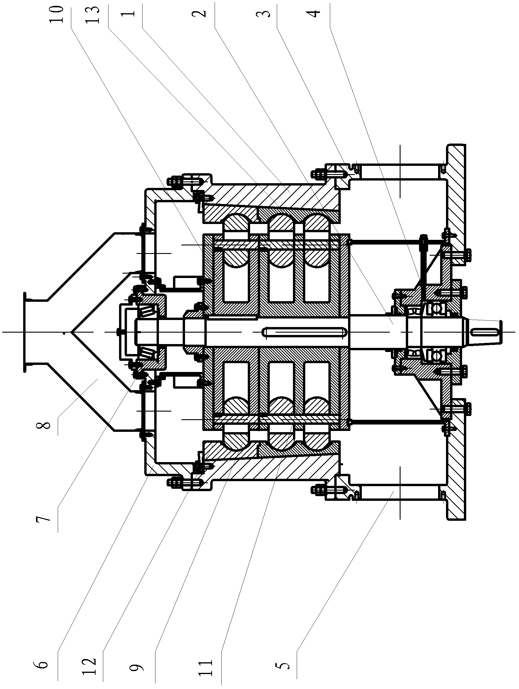
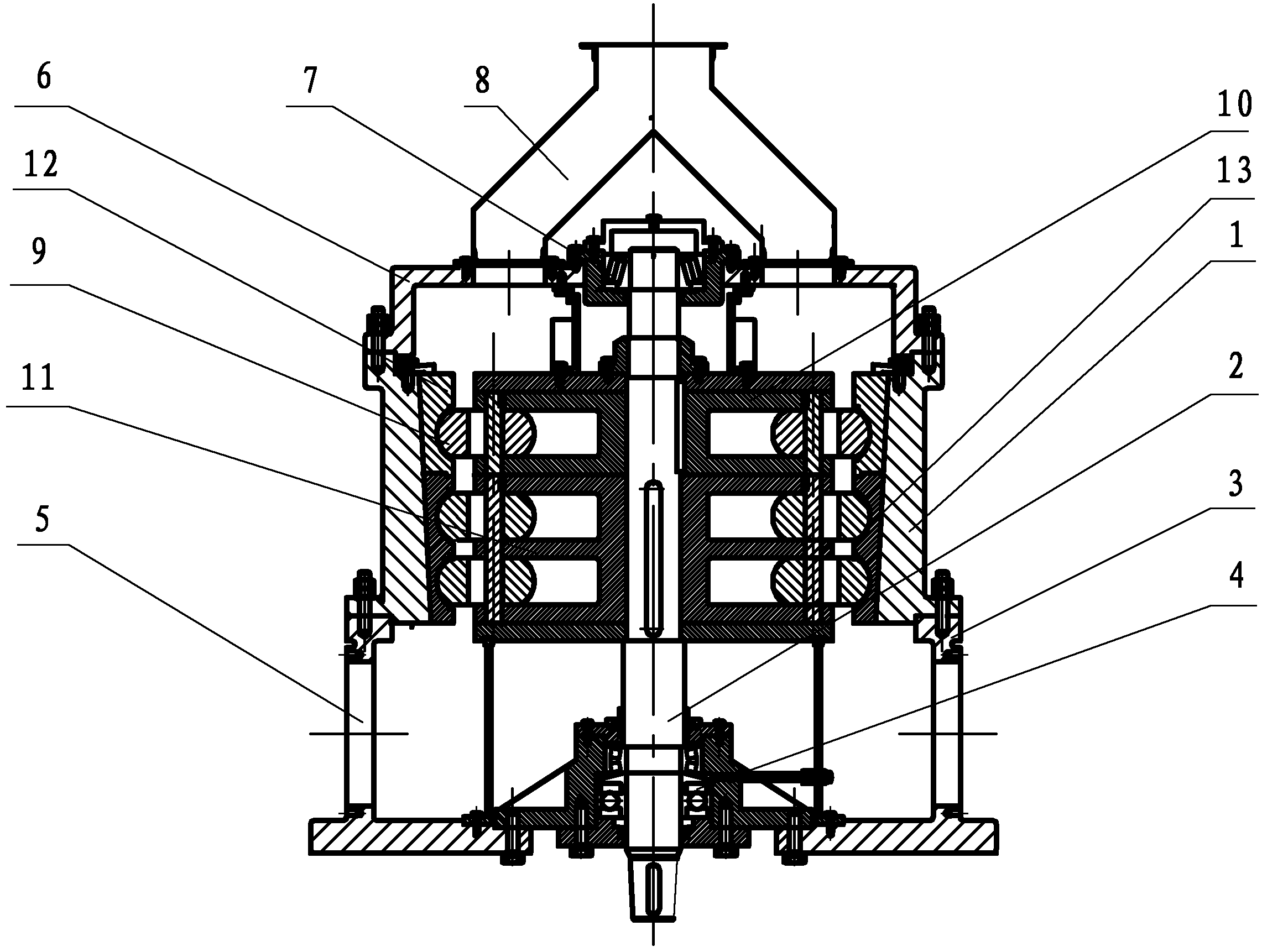
[0021] The milling machine of the direct-flow ultra-fine ring roller mill of the present invention comprises a main machine shell 1, a main machine upper cover 6, a main machine base 3, a main shaft 2, a grinding roller 9 and a grinding ring, and the upper and lower openings of the main machine shell 1 pass through flanges. Connect and install with the host upper cover 6 and the host base 3 respectively, the main shaft 2 is vertically placed on the central axis of the main machine casing 1, the upper and lower ends of the main shaft 2 are respectively supported and installed by the upper and lower bearing positions 7, 4, and the upper , the lower bearing positions 7, 4 are respectively arranged in the center of the main machine cover 6 and the main machine base 3, the grinding roller 9 is installed on the grinding roller frame, and the grinding roller fr...


PUM


Abstract

The invention discloses a straight-through type double-support ultra-fine ring roller grinder. The ring roller grinder comprises a grinding host, wherein the host shell of the grinding host is arranged on the a grinding host base; a grinding roller and a grinding ring, which are matched with each other, are arranged in the host shell; the grinding roller is arranged on a grinding roller support, and the grinding roller support is arranged on a main shaft; the lower end of the main shaft is in double-support arrangement through upper and lower bearing positions on a grinding host upper cover and the grinding host base; a negative-pressure gas port is formed on the grinding host base; the grinding ring is directly connected with the host shell in a seamless manner; and the gas port is communicated with a grader conveying pipe outside the grinding host. The grinding host is of a structure of feeding from the top and pumping at the bottom, is not restricted by the grading amount of the grader, and prevents discharge from leaking to the outside, so that more materials can be fed under the same using condition, the grinding efficiency is improved, mechanical collision and friction between the grinding roller and the grinding ring are lightened, and the grinding host has low noise.

Description

(1) Technical field: [0001] The invention relates to a powder processing equipment, in particular to a direct-flow double-support ultra-fine ring roller mill. (two) background technology: [0002] The mill processing system is traditionally used in my country for mineral powder crushing equipment, and it is widely used. [0003] Powder processing is divided into coarse powder, fine powder and ultra-fine powder processing. For example, the processing of 60 mesh or 400 mesh coarse powder or fine powder can be completed by Raymond machining system, but higher mesh powder should be collected (500 mesh to 3000 mesh or even higher), if the Raymond machine is still used for processing, the outstanding problems of the Raymond machine such as processing time, efficiency, vibration and noise are difficult to solve. Therefore, if you want to obtain finer or ultrafine powder, you need other structural types of mills, namely ring roller mills. [0004] This kind of ring roller mill ado...

Claims


Application Information

Patent Timeline
IPC IPC(8): B02C15/00
CPCB02C15/08
Inventor 肖先成
Owner GUILIN SHENGXING MACHINERY MFG
Learn More