Grid-connection control method of grid-side converter of small permanent magnet direct-driven wind power system

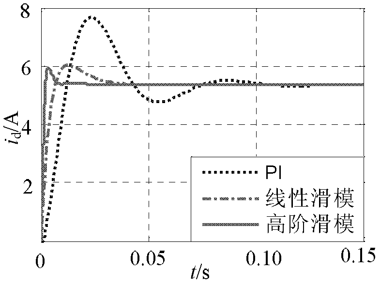
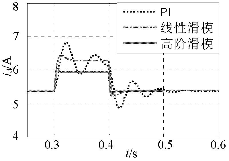
A grid-side converter, permanent magnet direct drive technology, applied in the direction of single grid parallel feeding arrangement, etc., can solve the problems of long system response time, large PI control overshoot, linear sliding mode control chattering phenomenon, etc. The effect of short system response time, small overshoot and superior dynamic performance

Inactive Publication Date: 2012-02-08
HARBIN INST OF TECH
View PDF3 Cites 6 Cited by
  • Summary
  • Abstract
  • Description
  • Claims
  • Application Information

AI Technical Summary

Problems solved by technology

[0003] The present invention aims to solve the problems of large overshoot, long system response time, and chattering phenomenon in the existing PI control, and proposes a grid-connected control of the grid-side converter of the small permanent magnet direct drive wind power system. method

Method used


Image

  • Grid-connection control method of grid-side converter of small permanent magnet direct-driven wind power system
  • Grid-connection control method of grid-side converter of small permanent magnet direct-driven wind power system
  • Grid-connection control method of grid-side converter of small permanent magnet direct-driven wind power system

Examples


specific Embodiment approach 1

[0015] Specific implementation mode 1. Combination Figure 7 Describe this specific implementation mode, the grid-connected control method of the grid-side converter of the small permanent magnet direct drive wind power system, and the specific method is as follows:

[0016] Step 1, collecting three-phase voltage signals and three-phase current signals of the power grid, and converting them into two-phase rotating voltage signals and two-phase rotating current signals;

[0017] Step 2. Obtain the given current of the d-axis

[0018] Step 3. According to the d-axis given current obtained in step 2 Get the d-axis high-order non-singular terminal sliding mode surface s 1 , given the current according to the q-axis Get the q-axis high-order non-singular terminal sliding mode surface s 2 ;

[0019] Step 4. According to the q-axis high-order non-singular terminal sliding mode surface s obtained in step 3 2 Get the q-axis control law u q , according to the d-axis high-orde...

specific Embodiment approach 2

[0021] Specific embodiment two, combine Figure 7 Describe this specific implementation mode. The difference between this embodiment mode and specific implementation mode 1 is that the specific method of step 1 is:

[0022] Step a, collecting three-phase static voltage signal e a 、e b 、e c , input into the Clark module, and output the two-phase static voltage signal e α 、e β , the three-phase static voltage signal e a 、e b 、e c Input the PLL module, output the position signal θ, and collect the three-phase static current signal i a i b i c , input into the Clark module, and output the two-phase quiescent current signal i α i β ;

[0023] Step b, the two-phase static voltage signal e α 、e β and the position signal θ are input to the Park module, and the two-phase rotating voltage signal e is output d 、e q , the two-phase quiescent current signal i α i β and the position signal θ are input to the Park module, and the two-phase rotating current signal i is outpu...

specific Embodiment approach 3

[0024] Specific embodiment three, combine Figure 7 Describe this specific embodiment. The difference between this embodiment and specific embodiment 1 is that the specific method of step 2 is: the d-axis outer ring sets the DC bus voltage Feedback d-axis outer loop DC bus voltage u dc Obtain the difference, the difference is adjusted by PI to form the given current of the d-axis inner ring


PUM


Abstract

The invention discloses a grid-connection control method of a grid-side converter of a small permanent magnet direct-driven wind power system, which relates to a grid-connection control method of a grid-side converter of a wind power system. The invention aims to solve the problems of large overshoot and long system response time of the traditional PI (Proportional Integral) control and a buffeting phenomenon existing in the linear sliding mode control. The concrete method comprises the following steps of: collecting a three-phase voltage signal and a three-phase current signal of a power grid and converting the three-phase voltage signal and the three-phase current signal into a two-phase rotating voltage signal and a two-phase rotating current signal; obtaining a d-axis given current, ad-axis high-order nonsingular terminal sliding mode surface s1 and a q-axis high-order nonsingular terminal sliding mode surface s2; obtaining a q-axis control law uq and a d-axis control law ud; andobtaining a drive signal of a grid-side converter, inputting the drive signal into the grid-side converter and converting the direct current generated by a permanent magnet direct-driven wind power system into alternating current for being input into the power grid by utilizing the grid-side converter. The method is used for the control of the grid-connection process of a wind power generator.

Description

technical field [0001] The invention relates to a grid-connected control method for a grid-side converter of a small permanent magnet direct-drive wind power system. Background technique [0002] During the grid-connection process of wind turbines, there will be problems such as overvoltage, overcurrent or speed increase, which will cause impact on the grid. The serious consequences of this impact will cause the voltage of the grid to drop, and will also cause damage to the generator and mechanical components. , what is more serious is that the long-term grid-connected impact may also cause the system to collapse or threaten the normal operation of the wind turbine. Therefore, it is necessary to suppress the grid-connected impact current through a reasonable generator grid-connected technology. The traditional control methods include PI control and linear sliding mode control, but PI control has a large overshoot, and the response time of the system is longer, while linear s...

Claims


Application Information

Patent Timeline
Patent Type & Authority Applications(China)
IPC IPC(8): H02J3/38
Inventor 郑雪梅李秋明王卫徐殿国郭玲李巍李晓磊
Owner HARBIN INST OF TECH
Why Eureka
Try Eureka