
System and method for controlling automotive lighting elements based on CAN (controller area network) data transmission

A lighting control system, automotive lighting technology, applied in vehicle components, transportation and packaging, circuits or fluid pipelines, etc. The effect of insecurity

Inactive Publication Date: 2012-02-08
重庆华福车船电子设备制造有限公司
View PDF5 Cites 3 Cited by
  • Summary
  • Abstract
  • Description
  • Claims
  • Application Information

AI Technical Summary

Problems solved by technology

However, there is no practical application in automotive lighting element control systems
[0003] If the indicator light is damaged while the car is driving, there will be unsafe hazards such as car collision
For example, when a car is turning, whether the front or rear turn signals are damaged, it is difficult to indicate the steering requirements to the adjacent drivers; when driving at night, if the width indicator lights are damaged, it is difficult to indicate to the adjacent drivers; In the process of driving, if the brake light of the car is damaged, it is easy to cause traffic accidents such as rear-end collision
The existing automotive lighting component control system has no corresponding emergency treatment measures, and can only be used again after the car is repaired

Method used


Image

  • System and method for controlling automotive lighting elements based on CAN (controller area network) data transmission
  • System and method for controlling automotive lighting elements based on CAN (controller area network) data transmission
  • System and method for controlling automotive lighting elements based on CAN (controller area network) data transmission

Examples


Embodiment Construction

[0028] The present invention will be further described below in conjunction with accompanying drawing.

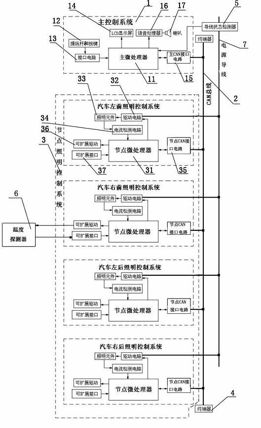
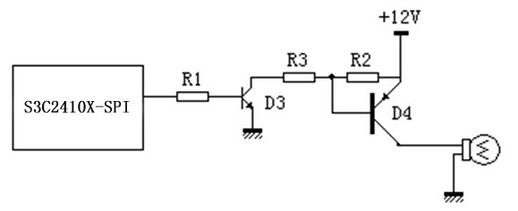
[0029] Such as figure 1 , figure 2 , image 3 , Figure 4 The shown automotive lighting control system based on CAN data transmission includes a main control system 1, a CAN bus 2, a node lighting control system 3 connected to the main control system 1 through the CAN bus 2, and terminators connected to both ends of the CAN bus 2 4. The power lead 7 for supplying power to the system and lighting components.

[0030] Main control system 1 comprises main microprocessor 11 (model S3C2410X—SPI), joystick and button 12, interface circuit 13, LCD display screen 14, speech processor 16, loudspeaker 17 and main CAN interface circuit 15; Joystick and button 12 is connected with the main microprocessor 11 through the interface circuit 13, and is sent to the main microprocessor 11 for analysis after converting different position states such as emergency and turning; the main micr...


PUM


Abstract

The invention discloses a system and method for controlling automotive lighting elements based on CAN (controller area network) data transmission. The system comprises a main control system, a CAN bus and a node lighting control system, wherein the node lighting control system is connected with the main control system by the CAN bus; the main control system sends a command to the node lighting control system, and receives feedback information of the node lighting control system; and the node lighting control system receives the command of the main control system, and sends the feedback information to the main control system so as to automatically replace the damaged lighting elements. The system and method disclosed by the invention can be used for detecting the states of the automotive lighting elements, prompting on damaged lighting elements and replacing the damaged lighting elements, thereby reducing the potential safety hazards of automobiles in the process of driving, and improving the safety of automotive lighting.

Description

technical field [0001] The invention relates to a control system and a control method of an automobile lighting element based on CAN data transmission. Background technique [0002] CAN (ControllerAreaNetwork) data bus is an automotive local area network suitable for automotive environments. It belongs to one of the multiplex transmission systems, a serial communication developed by the German Bosch company in the early 1980s to solve the data exchange between numerous control units and test instruments in modern automobiles protocol. Because it has the characteristics of fully distributed multi-machine system, multiple communications, high transmission reliability, strong security, no network failure, easy expansion and easy implementation, it is widely used in automobiles. However, it has no practical application in automotive lighting element control systems. [0003] If the indicator light is damaged during the driving of the car, there will be unsafe hidden dangers s...

Claims


Application Information

Patent Timeline
Patent Type & Authority Applications(China)
IPC IPC(8): B60Q1/00B60R16/02
Inventor 汤智鹏杨明建刘伟甘小林黎琼申林邹飞王庆平
Owner 重庆华福车船电子设备制造有限公司
Learn More