


Quick Research
Generate reliable direction feasibility study reports for your R&D in just a few steps.

Technical Q&A
Discover and master advanced knowledge NOW. Basics, ideas, possibilities, all at once.

Find Solutions
As an expert in R&D theories, this can generate solutions to your technical problems instantly.

Evaluate Feasibility
Analyze your overall solution with one click, know your potential R&D risks in advance.

Monitor Landscape
Get weekly tech updates, stay abreast of the latest tech innovations and key insights.
Two-dimensional discrete wavelet transform circuit and image compression method using same
A two-dimensional discrete wavelet and transform circuit technology, used in image communication, television, electrical components, etc., can solve the problems of complex VLSI structure and low hardware utilization, meet the requirements of reducing the capacity and quantity of off-chip memory, and reduce development. Difficulty and cost, the effect of improving data processing speed
- Summary
- Abstract
- Description
- Claims
- Application Information
AI Technical Summary
Problems solved by technology
Method used
Image

Examples
specific Embodiment approach 1
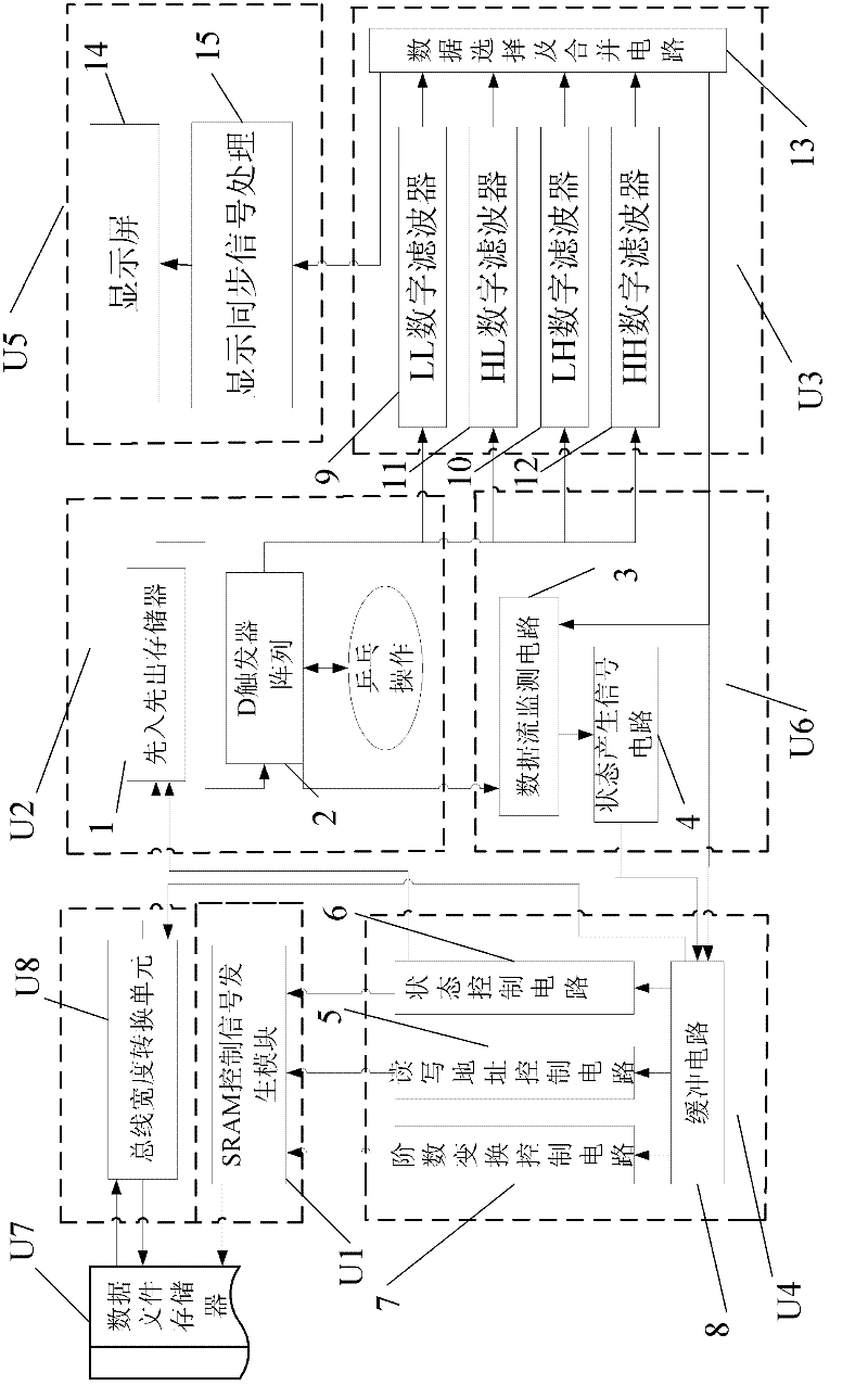
[0014] Specific implementation mode one: the following combination figure 2 and Figure 4 This embodiment will be specifically described. The two-dimensional discrete wavelet transform circuit of this embodiment includes a SRAM control signal generation module U1, a data rearrangement module U2, a wavelet transform module U3, a control module U4, a display control module U5, a state monitoring module U6, a data file memory U7, and a bus width Conversion module U8, data rearrangement module U2 includes first-in-first-out memory 1 and D flip-flop array 2, state monitoring module U6 is composed of data flow monitoring circuit 3 and state signal generation circuit 4, control module U4 is composed of read-write address control circuit 5 , state control circuit 6, order conversion control circuit 7 and buffer circuit 8, wavelet transform module U3 is composed of LL digital filter 9, LH digital filter 10, HL digital filter 11, HH digital filter 12 and digital selection and Combini...
specific Embodiment approach 2
[0015] Specific implementation mode two: the following combination figure 2 This embodiment will be specifically described. The difference between this embodiment and Embodiment 1 is that it also includes a display screen 14 and a display screen synchronous signal processing circuit 15, and the signal input end of the display screen synchronous signal processing circuit 15 is connected to another data output of the digital selection and merging circuit 13. terminal, the data output terminal of the digital selection and combining circuit 13 is connected to the data input terminal of the display screen 14 . With such setting, the data after discrete wavelet transformation can be displayed.
specific Embodiment approach 3
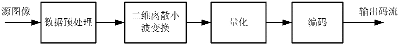
[0016] Specific implementation mode three: the following combination figure 1This embodiment will be specifically described. The image compression method of the present embodiment comprises the following steps: 1. Data preprocessing: the image is set in the scanning area of the wavelet transform window filter as the compression object; if the amount of data of the image is relatively large, the wavelet transform window filter The scanning area is divided into several areas of equal size, and each area is compressed independently to reduce the memory resources required for the compression process. If the memory is sufficient, compression can also be performed without dividing regions.
[0017] It is also possible to perform magnitude reduction on downsampled samples of compressed objects. The magnitude reduction is to subtract 2 from an unsigned integer with a sampling precision of P p-1 Make the original range [0, 2 p ] samples shifted to [-2 p-1 ,2 p-1 ] within the sc...
PUM
 Abstract
Description
Claims
Application Information
 - R&D Engineer
- R&D Manager
- IP Professional
- Industry Leading Data Capabilities
- Powerful AI technology
- Patent DNA Extraction
Browse by: Latest US Patents, China's latest patents, Technical Efficacy Thesaurus, Application Domain, Technology Topic, Popular Technical Reports.
© 2024 PatSnap. All rights reserved.Legal|Privacy policy|Modern Slavery Act Transparency Statement|Sitemap|About US| Contact US: help@patsnap.com