Coupled polarizing plate set and in-plane switching mode liquid crystal display including same

A liquid crystal display and polarizing plate technology, applied in the direction of instruments, optics, nonlinear optics, etc., can solve the problems of difficult to prepare thin products, difficult shrinkage steps, low economic benefits, etc., to ensure wide viewing angle and reduce defective rate Effect

Inactive Publication Date: 2012-01-18
DONGWOO FINE CHEM CO LTD
View PDF7 Cites 11 Cited by
  • Summary
  • Abstract
  • Description
  • Claims
  • Application Information

AI Technical Summary

Problems solved by technology

[0010] However, a liquid crystal display proposed in the related art uses a three-layer compensation film type coupled polarizing plate formed by laminating two layers having different optical properties on one side of a liquid crystal layer (one lower isotropic film + two upper Compensation layer), or it is difficult to have a large area Z-axis oriented film due to the lower economic efficiency and the necessary shrinking step to use the shrink film in the manufacturing process
[0011] Therefore, in the related art, since a coupled polarizing plate laminated with three compensation films is used, it is difficult to make a thin product because the thickness of the two sides of the liquid crystal cell is different, a change in temperature or humidity easily causes warping, and it is difficult to manufacture a thin product because of the expensive The compensation film leads to poor price competitiveness, and its use is limited to high-cost in-plane switching LCDs

Method used


Image

  • Coupled polarizing plate set and in-plane switching mode liquid crystal display including same
  • Coupled polarizing plate set and in-plane switching mode liquid crystal display including same
  • Coupled polarizing plate set and in-plane switching mode liquid crystal display including same

Examples


Embodiment 1

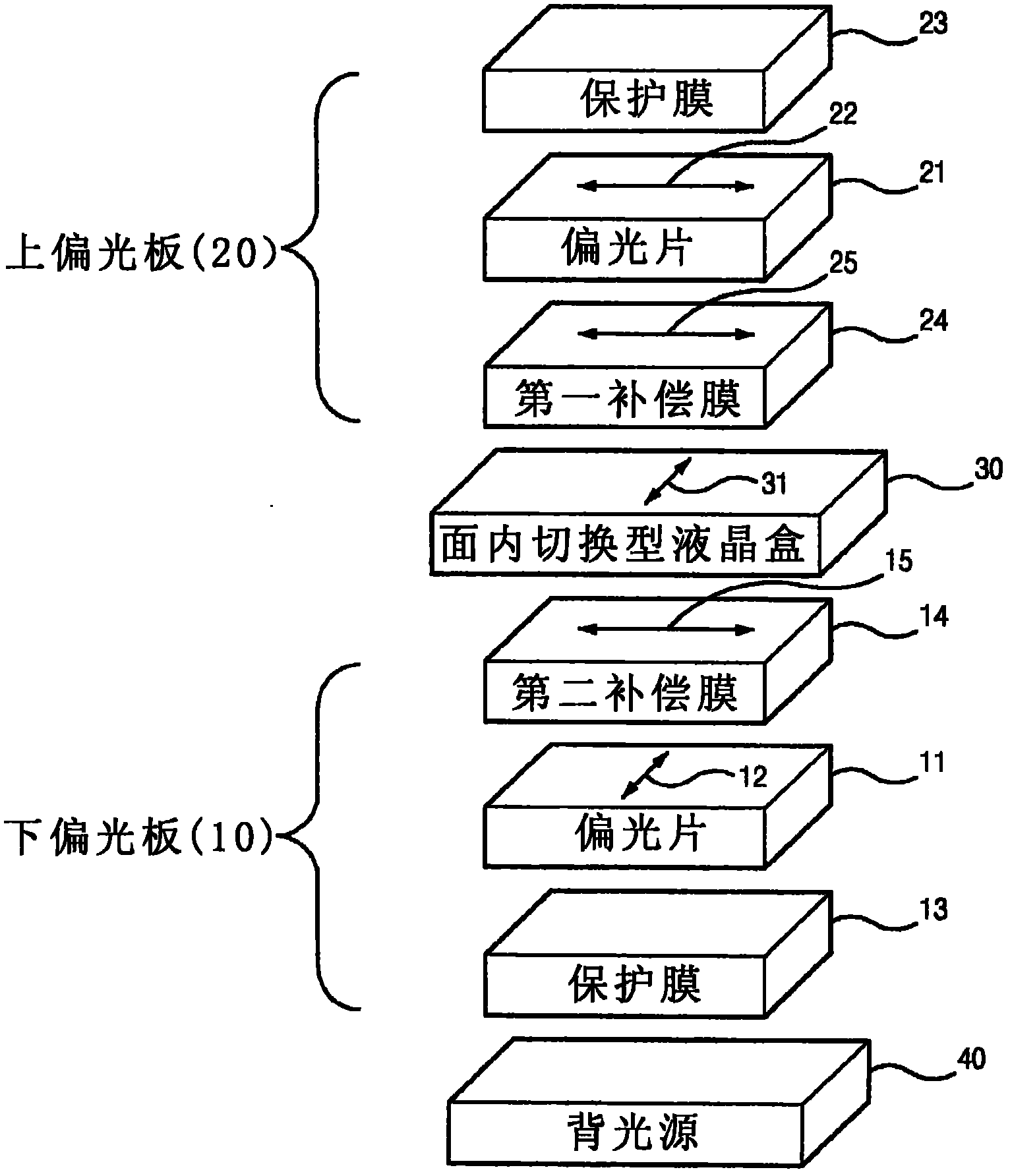
[0098] The actual measured data of each optical film, liquid crystal cell and backlight according to the present invention was used to have figure 1 TECH WIZ LCD 1D (Sanayi System Co., Ltd., Korea) of the laminated structure shown. It will be described in detail below figure 1 Structure.

[0099] Starting from the backlight unit 40, a lower polarizer 10, an in-plane switching type liquid crystal cell 30 (which has a liquid crystal orientation of 90° when viewed from the front of the display side when no voltage is applied) and an upper polarizer 20 are provided, in which , the lower polarizer 10 is formed by laminating the protective film 13, the polarizer 11 and the second compensation film 14 from the backlight unit 40, and the first compensation film 24, the polarizer 21 and the protective film 24 are laminated starting from the in-plane switching liquid crystal cell 30. The film 23 forms the upper polarizer 20 .

[0100] The liquid crystal cell is a liquid crystal cell ...

Embodiment 2

[0119] Although the same configuration as in Embodiment 1, the first compensation film 24 has an in-plane retardation (R0) of 100 nm and a refractive index ratio (NZ) of -0.1, and the second compensation film 14 has an in-plane retardation of 150 nm (R0) and -0.7 refractive index ratio (NZ). The sum of the in-plane retardation of the first compensation film 24 and the second compensation film 14 was 250 nm.

[0120] As a simulation result of the transmittance from all light directions, it is obtained as shown in Figure 10 results in . Figure 10 Displays the transmittance from all light direction distributions when the black state is displayed on the screen, where, within the range of the scale, when the black state is displayed, the transmittance is 0% to 0.2%, and the transmittance exceeds 0.02% The parts of the light are shown in red, and the low transmittance parts are shown in blue. In this case, it can be seen that the wider the blue portion in the center, the easier...

Embodiment 3

[0126] Although the same as the configuration in Embodiment 1, the first compensation film 24 has an in-plane retardation (R0) of 50 nm and a refractive index ratio (NZ) of -0.1, and the second compensation film 14 has an in-plane retardation (R0) of 250 nm and a refractive index ratio of -0.7. The sum of the in-plane retardation of the first compensation film 24 and the second compensation film 14 was 300 nm.

[0127] As a simulation result of the transmittance from all light directions, it is obtained as shown in Figure 13 results in . Figure 13 Displays the transmittance from all light directions when the black state is displayed on the screen, wherein, within the range of the scale, when the black state is displayed, the transmittance is 0% to 0.2%, and the transmittance exceeding 0.02% transmittance Parts are shown in red, and low transmittance parts are shown in blue. In this case, it can be seen that the wider the blue portion in the center, the easier it is to ens...


PUM

PropertyMeasurementUnit
transmittivityaaaaaaaaaa

Abstract

The present invention discloses a coupled polarizing plate set and an in-plane switching mode liquid crystal display including the coupled polarizing plate set. In detail, the present invention discloses a coupled polarizing plate set including compensation films designed to have specific optical properties to minimize color distortion in accordance with viewing directions and ensure a wide viewing angle in an in-plane switching mode, and a liquid crystal display including the coupled polarizing plate set and an in-plane switching mode liquid crystal. According to the liquid crystal display of the present invention, since a degree of distribution of changes in polarization state on a Poincare Sphere is small, color distortion in accordance with viewing directions can be minimized and a wide viewing angle can be ensured. Further, it is possible to ensure a wide viewing angle with only one sheet of compensation film for the upper polarizing plate and lower polarizing plate, such that it is possible to implement mass production of thin liquid crystal displays with high yield (reducing defect ratio due to foreign substances).

Description

technical field [0001] The present invention relates to a coupled polarizer assembly and an in-plane switching type liquid crystal display including the same, wherein when the coupled polarizer assembly is applied to an in-plane switching type liquid crystal display, it can minimize color distortion and ensure wide perspective. Background technique [0002] Liquid crystal displays (LCDs) and general image displays are widely used. However, despite its various excellent properties, a narrow viewing angle is considered its disadvantage. [0003] The modes of liquid crystal displays are classified according to the original arrangement of liquid crystals, the structure of electrodes and the properties of liquid crystals. Currently, the modes of liquid crystal displays commonly used are twisted nematic (TN) mode, vertical alignment (VA) mode and in-plane switching (IPS) mode. )model. In addition, it can be divided into a normal black (normal black) mode and a normal white (nor...

Claims


Application Information

Patent Timeline
Patent Type & Authority Applications(China)
IPC IPC(8): G02F1/13363G02F1/1335
CPCG02F1/134363G02F1/13363
Inventor 金奉春
Owner DONGWOO FINE CHEM CO LTD
Why Eureka
Try Eureka