
Charge pump and working method thereof

A technology of charge pump and charge transfer, which is applied in the field of related circuits, can solve problems such as reduction, and achieve the effect of increasing conversion efficiency and reducing output voltage ripple

Active Publication Date: 2012-01-18
SHANGHAI INST OF MICROSYSTEM & INFORMATION TECH CHINESE ACAD OF SCI
View PDF3 Cites 11 Cited by
  • Summary
  • Abstract
  • Description
  • Claims
  • Application Information

AI Technical Summary

Problems solved by technology

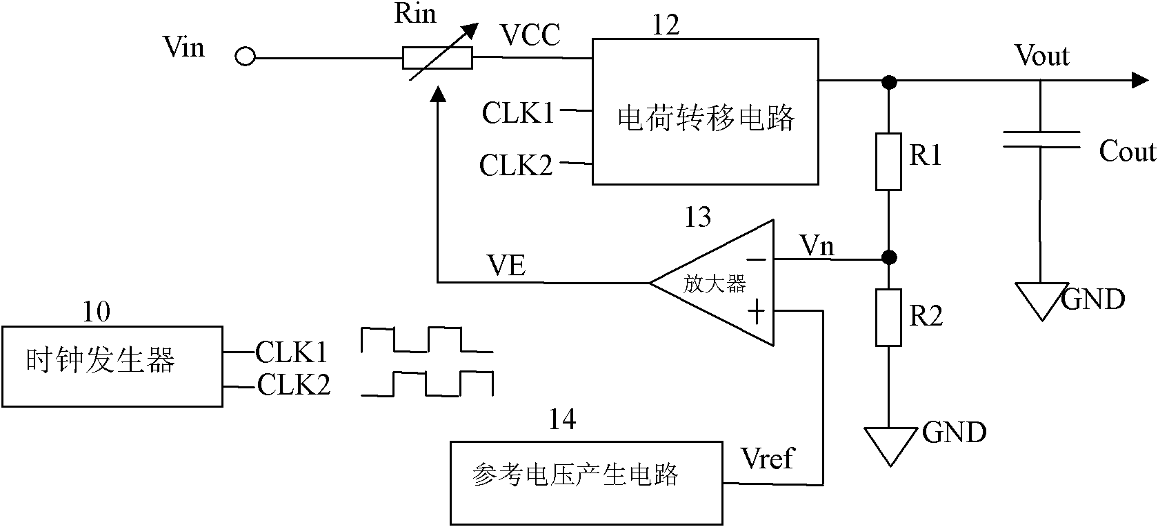
However, due to the internal resistance of the switch tube M1, the switch tubes 54, 55, 56 and the charge pump circuit, the output voltage Vout will decrease with the increase of the load current.

Method used


Image

  • Charge pump and working method thereof
  • Charge pump and working method thereof
  • Charge pump and working method thereof

Examples


Embodiment 1

[0031] Such as Image 6 As shown, the charge pump includes a reference voltage generating circuit 62, a voltage comparator 63, a clock generator 61, a charge transfer capacitor Cf, a voltage stabilizing capacitor Cout, a first switch M1, a second switch 65, a third switch 64, a Four switches 66; by charging the charge transfer capacitor Cf, and transferring the charge on the charged charge transfer capacitor Cf to the output terminal of the charge pump, outputting a level higher than the input voltage, each time the charge transfer capacitor Cf is charged , does not fully charge the charge transfer capacitor Cf, but stops charging after charging the charge transfer capacitor Cf to the set voltage.

[0032]In this embodiment, charge the charge transfer capacitor, when the plate voltage on the charge transfer capacitor reaches Vo-Vin+k (Vo-Vout), stop charging the charge transfer capacitor; where Vo is the expected voltage at the output end of the charge pump Value, Vin is the ...

Embodiment 2

[0044] Figure 8 As another example of the charge pump of the present invention, for Image 6 The implementation mode is further optimized. In this embodiment, the charge pump is composed of a clock generator 81, a reference voltage generating circuit 82, a voltage comparator 83, a power supply selection circuit 84, level conversion circuits 85, 86, an inverter 87, PMOS transistors M1, M2, M4, and NMOS The tube M3, the charge transfer capacitor Cf, and the voltage stabilizing capacitor Cout are formed.


PUM


Abstract

The invention discloses a charge pump and a working method thereof. The charge pump comprises a reference voltage generation circuit, a voltage comparator, a clock generator, a charge transferring capacitor, a voltage-stabilizing capacitor, a first switch, a second switch, a third switch and a fourth switch; through charging the charge transferring capacitor and transferring charges on the charged charge transferring capacitor to the output end of the charge pump, an electrical level higher than an input voltage is output, and when the charge transferring capacitor is charged every time, the charge transferring capacitor is not charged fully, but is only charged to a set voltage, and then the charging is stopped. According to the invention, the conversion rate of the charge pump can be increased, and the voltage ripples output by a circuit of the charge pump are reduced.

Description

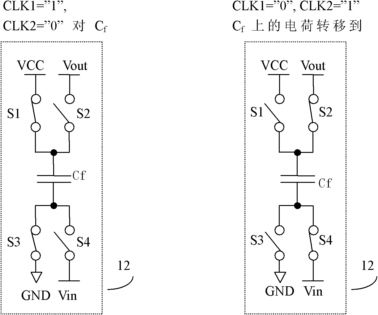
technical field [0001] The invention relates to the field of circuits, in particular to a charge pump and a working method. Background technique [0002] A charge pump is a circuit that outputs different voltages based on a single supply voltage, typically involving twice the input voltage. Charge pumps are often used in memory circuits, especially flash memory or phase change memory that require multiple voltages to read and write properly. [0003] Such as figure 1 as shown, figure 1 It is an existing charge pump circuit for generating high voltage Vout, the output voltage Vout can be controlled by setting the reference voltage Vref. The charge pump circuit is composed of a clock generator 10, a variable resistor Rin, a charge transfer circuit 12, voltage dividing resistors R1 and R2, a voltage amplifier 13 and a reference voltage generating circuit 14, wherein Vin is the input voltage of the charge pump circuit, CLK1 and CLK2 is a two-phase non-overlapping clock gener...

Claims


Application Information

Patent Timeline
Patent Type & Authority Applications(China)
IPC IPC(8): H02M3/07
Inventor 富聪宋志棠陈后鹏陈小刚
Owner SHANGHAI INST OF MICROSYSTEM & INFORMATION TECH CHINESE ACAD OF SCI
Learn More