
Bolt fastening state monitoring device and use method thereof

A condition monitoring device and bolt technology, which is applied in the measurement of elastic deformation force by measuring the gauge, etc., can solve the problem of the responsibility of the inspector, the dependence of the work attitude is relatively large, the damage of bolt loosening is not deep enough, and it is difficult to avoid sudden changes. Sexual incidents and other issues, to reduce the influence of human factors and dependence on human quality and other factors, save labor costs, and reduce manufacturing costs.

Active Publication Date: 2012-01-18
中国水利水电科学研究院机电所 +1
View PDF7 Cites 33 Cited by
  • Summary
  • Abstract
  • Description
  • Claims
  • Application Information

AI Technical Summary

Problems solved by technology

[0003] However, due to the lack of deep understanding of the hazards of bolt loosening in the past, effective monitoring methods have been lacking.
At present, there are two possible monitoring methods: regular or irregular patrol inspection is the easiest to think of, and its disadvantages are high cost, high dependence on the responsibility and work attitude of patrol inspectors, and it is difficult to avoid sudden incidents The other is to set up monitoring cameras at the bolts and bolt installation positions, and introduce video signals into the central control room for monitoring. The disadvantage is that the central control room may not be able to see clearly after the bolts are loose, and it is too dependent on the monitoring personnel.

Method used


Image

  • Bolt fastening state monitoring device and use method thereof
  • Bolt fastening state monitoring device and use method thereof
  • Bolt fastening state monitoring device and use method thereof

Examples


Embodiment Construction

[0016] The present invention will be described in detail below in conjunction with the accompanying drawings and embodiments.

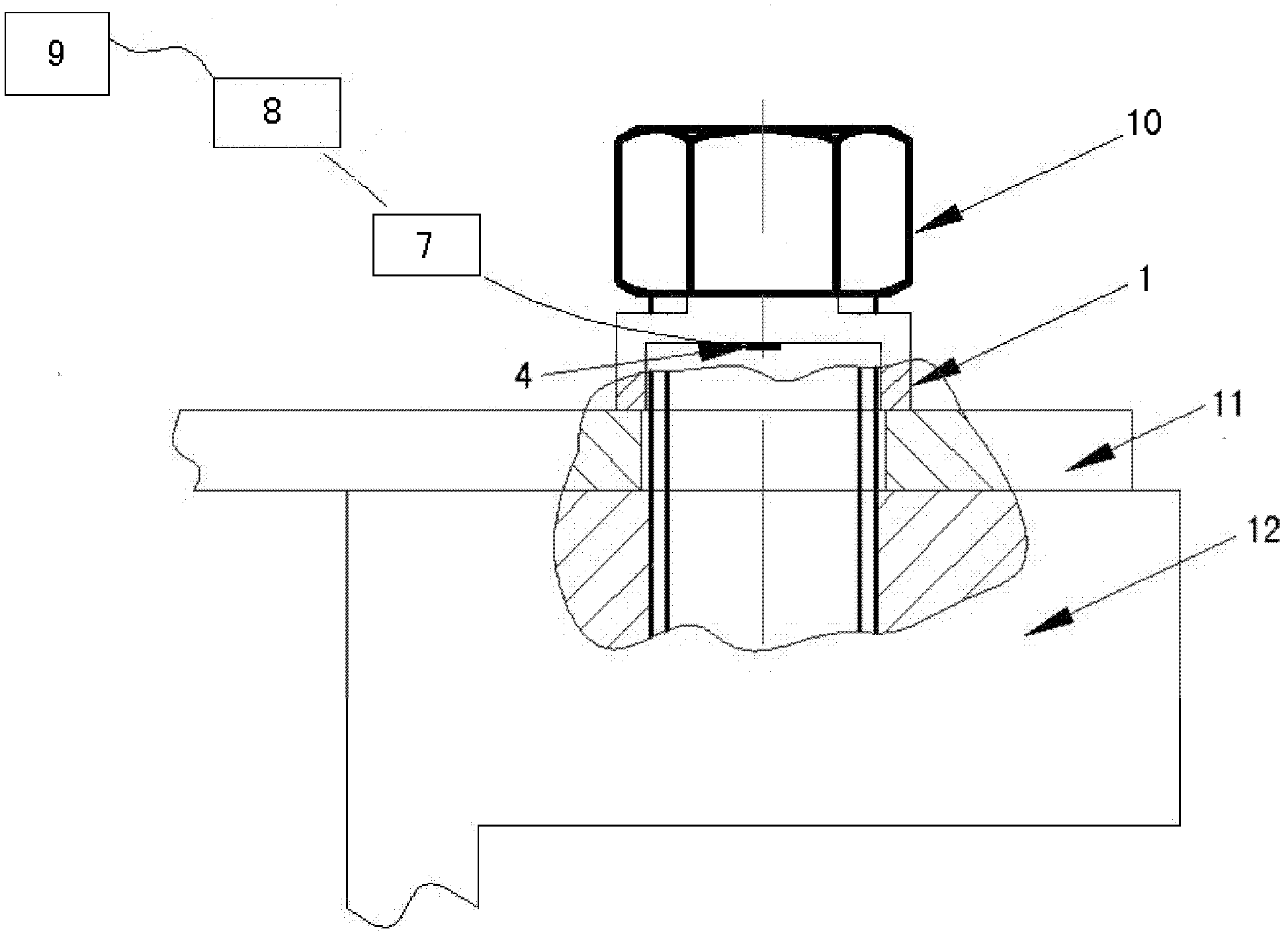
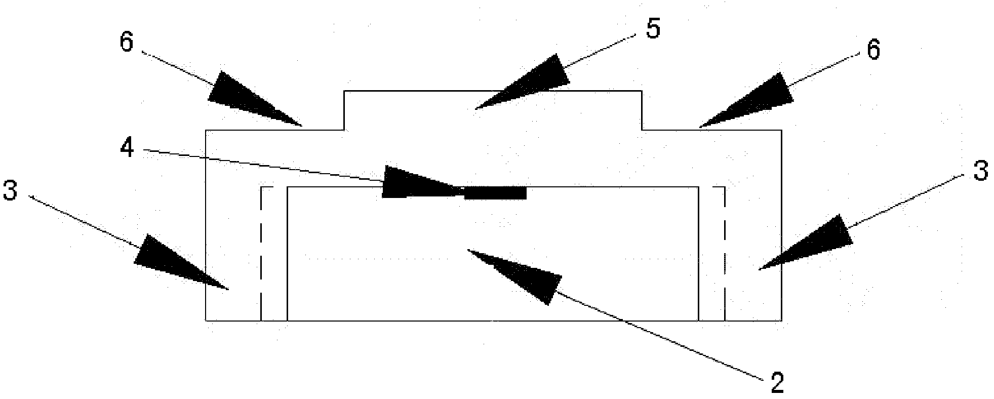
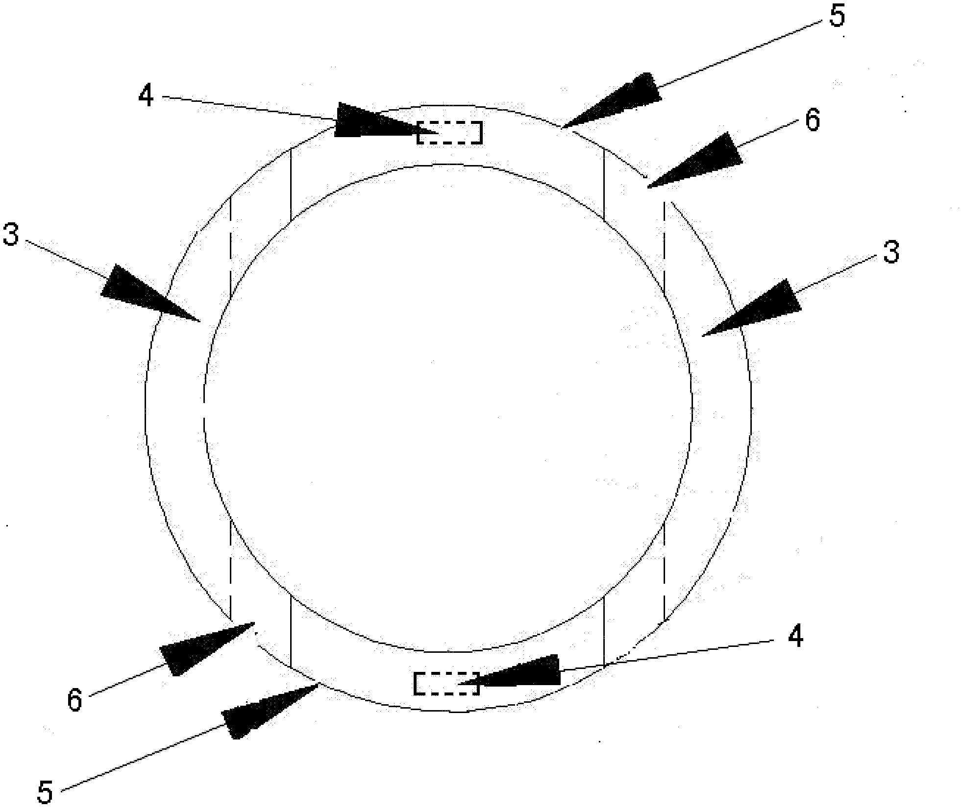
[0017] Such as figure 1 , figure 2 , image 3 As shown, the present invention includes an elastic washer 1 that is a ring cylinder, and a through groove 2 that runs through the ring cylinder is radially provided at the bottom of the elastic washer 1, so that two arc-shaped legs 3 are formed at the bottom of the elastic washer 1. A pressure strain gauge 4 is respectively arranged at the top center of the two notches of the through groove 2 between the two arc-shaped legs 3; slices or more. Two arc-shaped cylinders are cut off in parallel with the through groove 2 on both sides of the upper part of the elastic washer 1, so that two arc-shaped bosses 5 that are 90° to the arc-shaped legs are formed on the upper part of the elastic washer 1. At the same time, the width of the boss 5 is smaller than the width between the two arc-shaped legs 3, so that...


PUM


Abstract

The invention relates to a bolt fastening state monitoring device and a use method thereof. The device disclosed by the invention comprises a circular column elastic gasket, wherein the lower part of the elastic gasket is radially provided with a trough which penetrates through a circular column; the lower part of the elastic gasket form two arc-shaped landing legs; the top of the mouth of the trough is provided with a pressure strain gauge; two sides of the upper part of the elastic gasket are provided with two sections of arc-shaped notches in parallel with the trough; the upper part of theelastic gasket forms two arc-shaped bosses which form an angle of 90 degrees with the arc-shaped landing legs; the pressure strain gauge is connected with a signal amplifier by virtue of a lead; the signal amplifier is connected with a data acquisition device by virtue of a data line; the data acquisition device is connected with the original computer monitoring equipment by virtue of a data line; and the computer monitoring equipment compares a data signal value collected at fixed period with a preset alarming threshold value so as to judge whether an alarming measure is adopted. The bolt fastening state monitoring device has the advantages of being low cost, safe to operate and almost free from manual participation, and can be widely applied to the production and scientific research fields of hydropower stations and the like which comprise pressure containers and need to fasten bolts.

Description

technical field [0001] The present invention relates to a monitoring device and its use method, in particular to a monitoring device and its use method for monitoring the status of bolts (or nuts, hereinafter referred to as bolts) fastened on electromechanical equipment. Background technique [0002] With the rapid development of science and technology, the installed capacity of hydropower stations at home and abroad has a tendency to increase continuously, and the capacity of a single unit is also increasing. The increase of stand-alone capacity can greatly reduce the project cost and reduce the cost, but it may also reduce the stability due to the reduction of relative stiffness, induce accidents, and may even cause more serious damage. For example, on August 17, 2009, a serious accident occurred at the Sayan-Shushensk Hydropower Station in Russia. Afterwards, the accident investigation organized by the Russian government concluded that: "The damage of the bolts caused by ...

Claims


Application Information

Patent Timeline
IPC IPC(8): G01L1/04
Inventor 徐洪泉王万鹏唐拥军陆力潘罗平李铁友廖翠林瞿军穆恩良
Owner 中国水利水电科学研究院机电所
Learn More