Interface device, imaging system and method for rim-imaging

A technology of an interface device and an imaging system, which can be used in the fields of instruments and applications for radiological diagnosis, ultrasound/sonic/infrasonic Permian technology, etc., and can solve problems such as difficulties

Inactive Publication Date: 2012-01-11
KONINKLIJKE PHILIPS NV
View PDF3 Cites 4 Cited by
  • Summary
  • Abstract
  • Description
  • Claims
  • Application Information

AI Technical Summary

Problems solved by technology

Therefore, tomography or tomography becomes difficult, if not impossible

Method used


Image

  • Interface device, imaging system and method for rim-imaging
  • Interface device, imaging system and method for rim-imaging
  • Interface device, imaging system and method for rim-imaging

Examples


Embodiment Construction

[0036] The illustrations in the figures are exemplary and not drawn to scale. In different drawings, similar or identical elements have the same reference numerals.

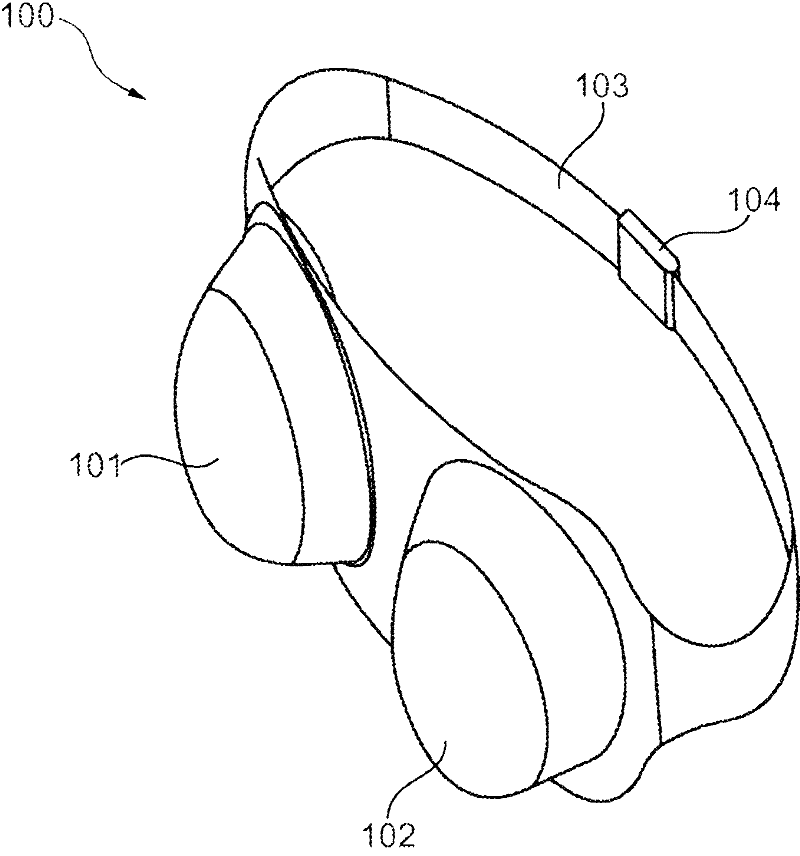
[0037] figure 1 An interface device for phase-contrast edge imaging of an object of interest, in particular for mammographic imaging of two female breasts, is shown.

[0038] The device 100 comprises two containers 101, 102, the first for the patient's right breast and the second for the patient's left breast.

[0039] Furthermore, the device 100 comprises a strap 103 for forcing the containers 101, 102 against the breast and for tightening the device around the patient's breast. Furthermore, a clasp 104 is provided for opening and fastening the strap 103 .

[0040] The straps 103 allow for adjustment of the force of the device 100 against the breast to suit the patient's comfort. The containers 101 , 102 may be at least partially flexible to allow them to change shape according to the boundaries defining the...


PUM


Abstract

The invention relates to imaging systems in which during imaging of an object a matching medium is used to match the object to its surroundings. An interface device is used for phase contrast rim-imaging of the object, which comprises a compartment in which a deformable matching material is contained which can be pushed to the side when the object to be imaged is compressed. Thus, a lateral field of view for X-ray phase contrast mammography may be increased.

Description

technical field [0001] The present invention relates to an interface device for phase contrast fringe imaging of an object of interest, a mammography imaging system and a method for phase contrast fringe imaging of an object of interest. Background technique [0002] Radiographic phase-contrast mammography has the potential to significantly improve the diagnostic value of mammograms. A particular problem with phase contrast imaging is the so-called phase wrapping problem. For example, when using a phase grating with p 1 In the measurement setup of the pitched Talbot interferometer, only the gradient of the phase front is less than 2π / p 1 , the phase information can only be unambiguously retrieved. This is usually achievable with soft tissues of constant thickness of a few centimeters (cm). However, this is generally not the case at the edges of the object to be imaged (object of interest), where there is a strong jump in the complex refractive index due to the tissue-air...

Claims


Application Information

Patent Timeline
Patent Type & Authority Applications(China)
IPC IPC(8): A61B5/00A61B6/00A61B6/04A61B8/08
CPCA61B5/0091A61B6/484A61B6/0414A61B8/0825A61B6/502
Inventor T・克勒
Owner KONINKLIJKE PHILIPS NV
Why Eureka
Try Eureka