Control method and system for hydraulic control device of continuously variable speed transmission of hybrid power system

A compound power and control device technology, applied in the direction of transmission control, power device, air pressure power device, etc., can solve problems such as poor efficiency, inability to obtain power output results, and inability to fully respond to various vehicle conditions

Active Publication Date: 2012-01-11
IND TECH RES INST
View PDF8 Cites 3 Cited by
  • Summary
  • Abstract
  • Description
  • Claims
  • Application Information

AI Technical Summary

Problems solved by technology

[0002] In the early known continuously variable transmission (CVT), the centrifugal block is placed in the movable half wheel of the driving wheel. The centrifugal block can only respond to the rotational speed of the engine to change the rotational pitch of the driving pulley, resulting in the rotational speed of the rear axle and The change of torque, this kind of speed change method cannot fully respond to various vehicle conditions, and it cannot obtain the best power output result. Because of its simple structure, it is mostly used on motorcycles, and its main disadvantages are small torque and poor efficiency.

Method used


Image

  • Control method and system for hydraulic control device of continuously variable speed transmission of hybrid power system
  • Control method and system for hydraulic control device of continuously variable speed transmission of hybrid power system
  • Control method and system for hydraulic control device of continuously variable speed transmission of hybrid power system

Examples


Embodiment Construction

[0070] In order to have a further cognition and understanding of the features, purpose and functions of the present invention, the relevant detailed structure and design concept of the device of the present invention will be described below, so that the characteristics of the present invention can be clearly understood, and the detailed statement as follows:

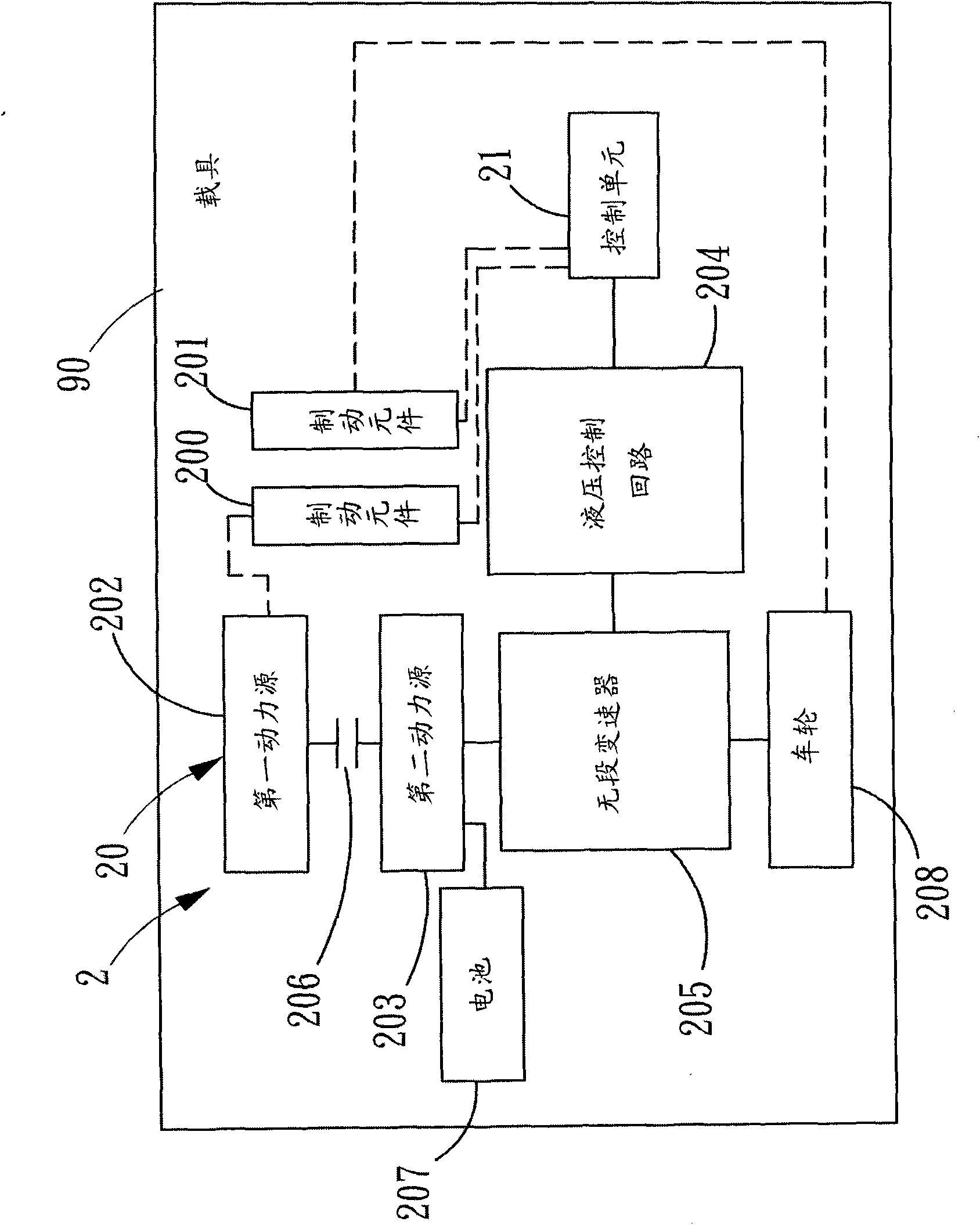
[0071] see figure 1 As shown, this figure is a schematic diagram of the control system of the hydraulic control device of the compound power system continuously variable transmission of the present invention. The control system 2 includes a hybrid power system 20 having two control components. In this embodiment, the control components are respectively an actuating component 200 and a braking component 201 on a carrier 90 . The carrier 90 is a wheeled vehicle, but it is not limited thereto, as long as it is a mobile tool that needs to utilize compound power, it can be the aspect covered by the carrier of the present in...


PUM


Abstract

The invention discloses a control method and system for a hydraulic control device of a continuously variable speed transmission of a hybrid power system. A variable speed adjusting device of the continuously variable speed transmission of the hybrid power system is used for changing the rotating speeds of an input shaft and an output shaft which are respectively coupled with a first liquid pump and a second liquid pump by using hydraulic pressure generated by the first liquid pump and the second liquid pump through a hydraulic loop. The control method and system which are disclosed by the invention are matched with an operation mode and state of the hybrid power system to select a series or parallel hydraulic loop so as to effectively control the output of the continuously variable speed transmission. Further, hydraulic pressure of the first liquid pump and the hydraulic pressure of the second liquid pump are controlled and the transmission ratio of the continuously variable speed transmission is controlled, so that input power sources (engines and motors) work in an optimal efficiency area to further reduce consumption of energy sources.

Description

technical field [0001] The invention relates to a stepless speed change control method and system, in particular to a control method and system for a hydraulic control device of a stepless speed changer in a compound power system. Background technique [0002] In the early known continuously variable transmission (CVT), the centrifugal block is placed in the movable half wheel of the driving wheel. The centrifugal block can only respond to the rotational speed of the engine to change the rotational pitch of the driving pulley, resulting in the rotational speed of the rear axle and The change of torque, this kind of speed change method cannot fully respond to various vehicle conditions, and it cannot obtain the best power output result. Because of its simple structure, it is often used on motorcycles, and its main disadvantages are small torque and poor efficiency. [0003] The new speed change mechanism is a metal belt type, which can increase the transmission torque, and th...

Claims


Application Information

Patent Timeline
Patent Type & Authority Applications(China)
IPC IPC(8): B60K6/543B60K6/36B60K6/44F16H61/42F16H61/66
CPCY02T10/623Y02T10/6243Y02T10/62
Inventor 谢凯清古焕隆魏增德
Owner IND TECH RES INST
Why Eureka
Try Eureka