Transmission method and device of uplink control signaling
A technology for control signaling and control channels, applied in wireless communication, error prevention/detection using return channels, electrical components, etc. Guaranteed to work properly
- Summary
- Abstract
- Description
- Claims
- Application Information
AI Technical Summary
Problems solved by technology
Method used
Image
Examples
Embodiment 1
[0094] In this embodiment, the uplink control signaling of the M2M terminal is carried by two channels, the PUCCH and the PUSCH.
[0095] When the bandwidth supported by the M2M terminal is smaller than the bandwidth of the LTE system, the uplink control signaling of the M2M terminal is carried in the uplink data (PUSCH) area of the LTE system, such as Figure 5 shown. The bearer mode and other mechanisms adopted may be the same as those of the existing LTE system and have compatibility, that is, the uplink control signaling of the M2M terminal is carried in two ways, the PUCCH and the PUSCH.
[0096] Wherein, the working bandwidth of the MTC device may be at a high frequency position, a low frequency position or a center frequency position within the system bandwidth. Figure 5 Indicated by the position of the center frequency. The advantage of this embodiment is that it will not affect the control area of the existing LTE system, thus not affecting the sending and rece...
Embodiment 2
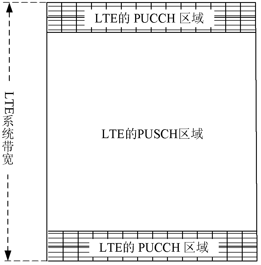
[0098] In this embodiment, the uplink control signaling of the M2M terminal is still carried by two channels, the PUCCH and the PUSCH. The bandwidth position of the M2M terminal is continuous with the PUCCH resource of the current LTE system in the frequency domain, such as Image 6 and Figure 7 As shown, the transmission resource occupied by the uplink control signaling of the MTC device may be continuous with the high-frequency or low-frequency PUCCH resource in terms of frequency. In order to ensure that resources are continuous and the location of M2M resources is known, a known number of PUCCH resources can be reserved for the LTE system, and the resources can be configured semi-statically through high-layer signaling.
[0099] The advantage of this embodiment is that it will not cause too many uplink resource fragments in the existing LTE system, and it can ensure that the terminal users of the existing LTE system can transmit large-bandwidth uplink data, and have litt...
Embodiment 3
[0101] In this embodiment, the uplink control signaling of the M2M terminal can be carried on the data channel and the control channel, and the data channel carrying mode can be the same as the existing mechanism.
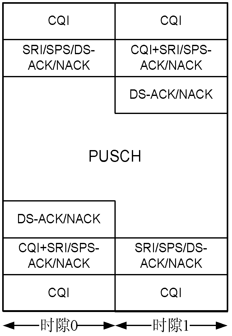
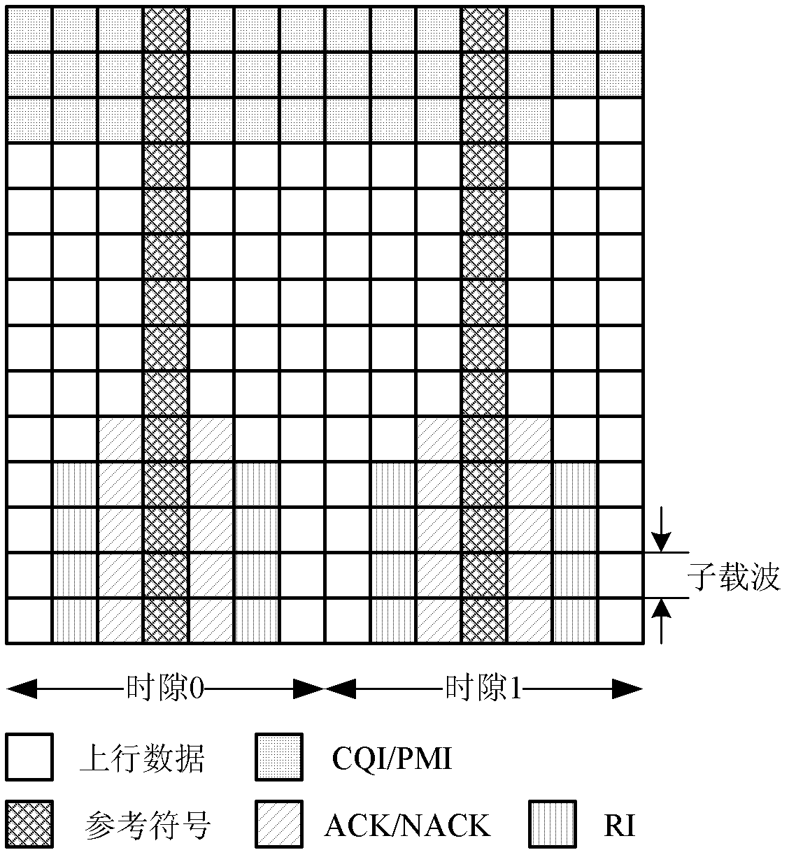
[0102] In addition, the uplink control signaling of the M2M terminal can be carried on the control channel, and the control channel is located at one end of the frequency band within the operating bandwidth of the MTC device, such as Figure 8 and Figure 9 shown.
[0103] Assuming that the new control channel is named X-PUCCH, then:
[0104] One way for the X-PUCCH control channel to carry control signaling is to use the PUCCH mapping and multi-user multiplexing coding methods of the existing LTE system, but instead of frequency hopping within the entire system bandwidth, it can hop within the resources occupied by the PUCCH frequency.
[0105] Another way for the X-PUCCH control channel to carry control signaling is to use the PUSCH mapping and multi-user mult...
PUM
 Abstract
Description
Claims
Application Information
 - R&D
- Intellectual Property
- Life Sciences
- Materials
- Tech Scout
- Unparalleled Data Quality
- Higher Quality Content
- 60% Fewer Hallucinations
Browse by: Latest US Patents, China's latest patents, Technical Efficacy Thesaurus, Application Domain, Technology Topic, Popular Technical Reports.
© 2025 PatSnap. All rights reserved.Legal|Privacy policy|Modern Slavery Act Transparency Statement|Sitemap|About US| Contact US: help@patsnap.com


