
Sole with drainage fan blades

A technology for fan blades and shoe soles, which is applied to shoe soles, footwear, applications, etc. It can solve the problems of difficult drainage and poor slip resistance of shoe soles, and achieve the effects of accelerating fluidity, improving adhesion, and increasing friction coefficient

Active Publication Date: 2012-01-04
MAOTAI FUJIAN SOLES CO LTD
View PDF6 Cites 5 Cited by
  • Summary
  • Abstract
  • Description
  • Claims
  • Application Information

AI Technical Summary

Problems solved by technology

[0003] In order to solve the defects that the general shoe soles are not easy to drain and have poor anti-slip performance, the present invention provides a shoe sole with drainage fan blades, which can quickly drain the accumulated water on the sole and play an anti-slip effect, so that it is more suitable for practical use.

Method used


Image

  • Sole with drainage fan blades
  • Sole with drainage fan blades
  • Sole with drainage fan blades

Examples


Embodiment 1

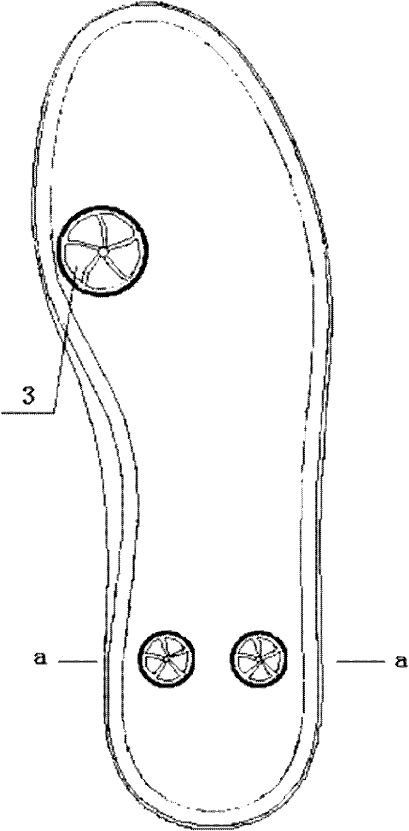
[0025] Depend on figure 1 As shown, there are three grooves 1 distributed sequentially from the toe to the heel on the bottom surface of the sole of the present embodiment, figure 1 The groove in the groove is circular, and of course it can also be elliptical or other special-shaped. The center of the bottom surface of each groove 1 is provided with five spirally distributed fan blades 3 that radiate outward. figure 1 There is only one layer of fan blades 3, of course it can be two or more layers of fan blades 3 spirally distributed, there are gaps 4 between the fan blades 3, each fan blade 3 is a petal-shaped structure, and each fan blade 3 adjacent The slits 4 are formed between the inner edges, and each slit 4 has the same bending direction, forming the spiral distribution; the outer edge of each fan blade 3 forms a circular edge. Depend on image 3 which is figure 1 As shown in the sectional view of the a-a section in the middle, the fan blade 3 forms a hollow ball tabl...

Embodiment 2

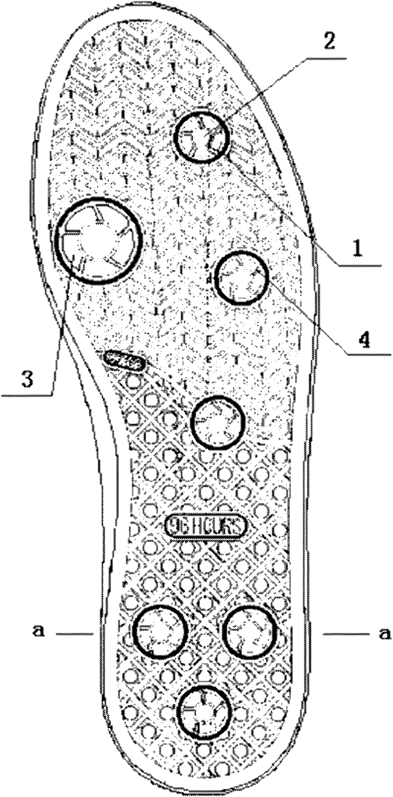
[0028] Depend on figure 2 As shown, seven circular grooves 1 are distributed sequentially from the toe of the shoe to the bottom of the heel in this embodiment, and each groove 1 has a circular protrusion 2 in the center, so that water will not accumulate in the center. Five spiral fan blades 3 radiate outward, and the inner surface of each fan blade 3 is bent inward to form a concave structure, and gaps 4 are left between the fan blades 3 . Depend on Figure 4 which is figure 2 As shown in the sectional view of the a-a section in the middle, the fan blade 3 forms a hollow ball table as a whole and the outer edge protrudes from the bottom surface of the sole, and the diameter of the outer edge of the fan blade 3 is slightly smaller than the diameter of the groove 1 . There are also non-slip and decorative textures on the sole surface. When the user wears the shoes and walks on the ground with a lot of water, the water enters the groove 1 and is squeezed between the shoes ...


PUM

PropertyMeasurementUnit
Gap widthaaaaaaaaaa

Abstract

The invention relates to a sole with drainage fan blades, which is characterized in that: a plurality of round grooves are distributed on the bottom surface of the sole; a plurality of spiral fan blades are radially arranged in the grooves towards the outer side of the bottom surface; each fan blade is made of an elastic material; the outer edge of each fan blade protrudes the bottom surface of the sole in a natural state; a round edge is formed on the outer edge of each fan blade; the diameter of each round edge is smaller than that of each groove; and gaps are reserved among the fan blades. When a large amount of water is accumulated on the ground, the water is extruded from the gaps among the spiral fan blades through the extrusion of the sole and the ground after entering the grooves, so that the fluidity of the water is increased, the area of the water contacting feet is reduced, the adhesion of the sole and the ground is improved, the friction coefficient of the sole is increased, and an anti-skid effect is achieved; and obvious technological progress is made, and an effect of making the sole more suitable to be used is achieved.

Description

technical field [0001] The invention relates to a shoe sole, in particular to a shoe sole capable of effectively draining water and preventing slipping. Background technique [0002] The structure of the existing traditional sole is mainly to manufacture a complete sole through rubber or plastic material, and various functional anti-skid patterns are arranged on the bottom surface of the sole. However, looking at the current sole structure, the part on the bottom surface of the sole is basically a flat closed structure state. Even if there are patterns that can play an anti-slip effect, when there is a lot of water on the ground such as bathrooms, kitchens or rainy environments, Water is easy to accumulate in the pattern of the sole, which greatly weakens the anti-skid effect and reduces the ground adhesion, which is easy to cause the wearer to slip or even slip, which brings great inconvenience. Contents of the invention [0003] In order to solve the defects of poor dra...

Claims


Application Information

Patent Timeline
IPC IPC(8): A43B13/22
Inventor 丁思恩
Owner MAOTAI FUJIAN SOLES CO LTD
Learn More