
Auto generator stator core winding body

A technology for automotive generators and stator cores, applied in the manufacture of stator/rotor bodies, etc., can solve problems such as difficult winding, difficult mass production, and unstable winding operation, and achieve stable winding operation and good product quality.

Active Publication Date: 2011-12-28
锦州新万得汽车部件有限公司
View PDF3 Cites 0 Cited by
  • Summary
  • Abstract
  • Description
  • Claims
  • Application Information

AI Technical Summary

Problems solved by technology

[0003] The problems of this kind of winding machine are: 1. If the size of the arc-shaped groove on the outside of the iron core strip is relatively shallow or the thickness of the iron core strip is thin (for example, 0.5mm), it will be more difficult to wind. It is difficult to carry out mass production to ensure the meshing of the convex circle and the arc groove; 2. It is impossible to wind the iron core strip without the arc groove on the outside; 3. Since the winding wheels (ie centering wheels) on both sides are The driving wheel in the middle drives the strip material to run and rotate, so the winding wheels on both sides interfere with each other, and the winding operation is not stable enough

Method used


Image

  • Auto generator stator core winding body
  • Auto generator stator core winding body
  • Auto generator stator core winding body

Examples


Embodiment Construction

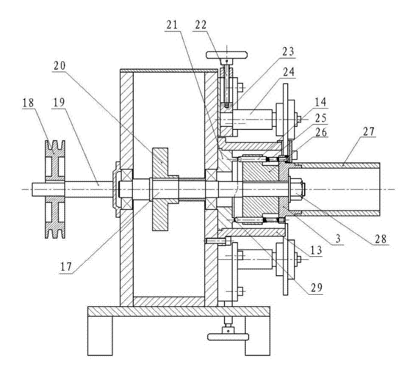
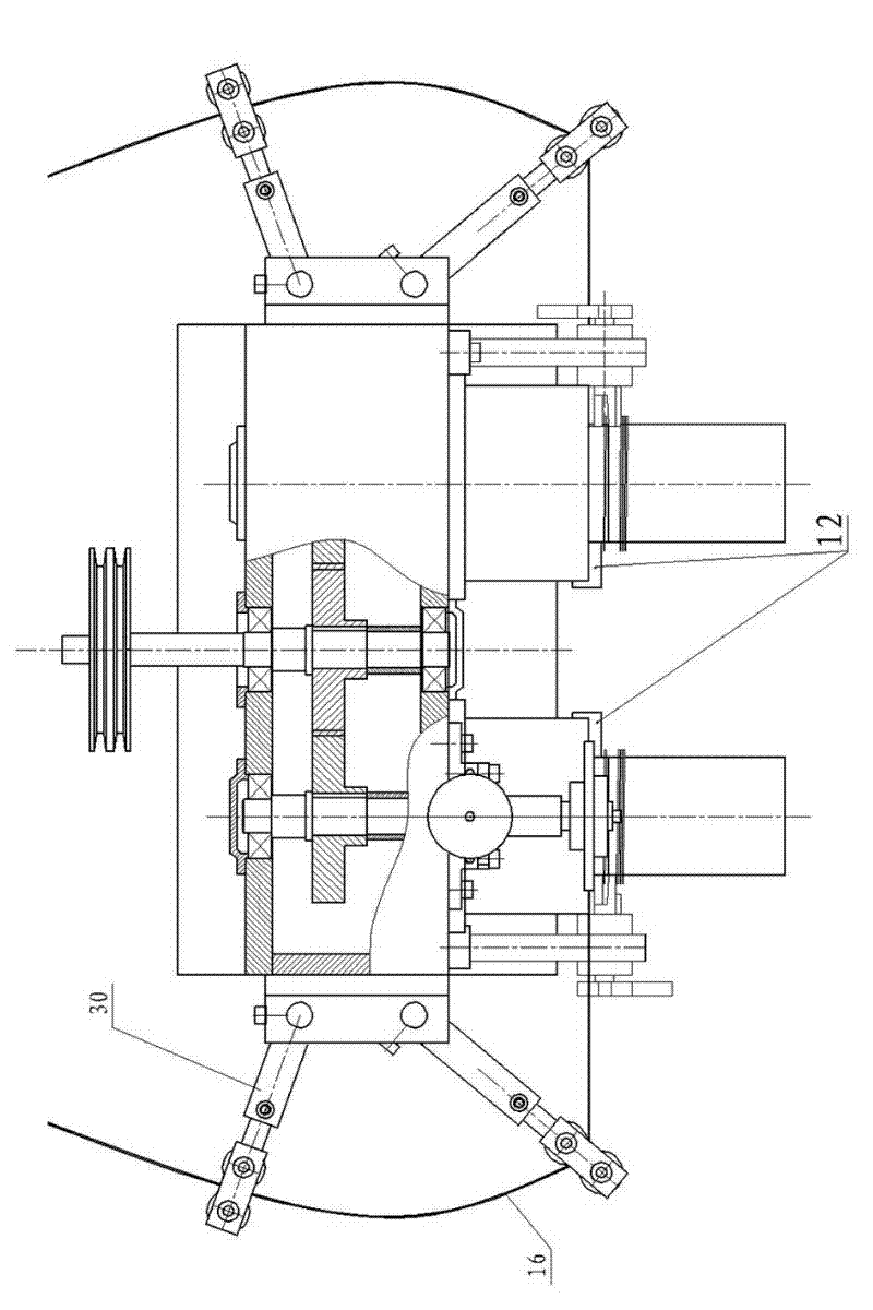
[0026] The automobile generator stator core winding machine body involved in the present invention includes a machine base 1 and a box body 2 fixed on the machine base 1, and a group of nearly tangential pressing wheels 10 and winding wheels 3 are respectively arranged on both sides of the front of the box body 2. , the pressure wheel 10 on the left is above the winding wheel 3 , and the pressure wheel 10 on the right is below the winding wheel 3 . A transmission shaft 19 and two winding wheel shafts 17 are installed in parallel through bearings in the box body 2, and the two winding wheel shafts 17 are symmetrically arranged on both sides of the transmission shaft 19 and are respectively connected with the transmission shaft 19 through a gear or a chain transmission mechanism. In this embodiment, the gear transmission mechanism 20 is taken as an example. The passive gears on the two winding axles 17 are of the same size and mesh with the driving gear on the transmission shaft ...


PUM


Abstract

The invention discloses a winding machine body for an automobile generator stator core. The machine body comprises a box body, wherein the two sides of the front surface of the box body are respectively provided with a group of pressing wheels and winding wheels; and the parts, adjacent to the winding wheels, of the front surface of the box body, are respectively provided with a shearing device. The machine body provided by the invention is characterized in that a transmission shaft and two winding wheel shafts are arranged in the box body, the two winding wheel shafts are respectively connected with the transmission shaft, and the winding wheels are respectively fixed at the front ends of the winding wheel shafts; top wheels are sleeved on the winding wheel shafts, winding pin wheels arefixed on the winding wheel shafts, winding pins are uniformly distributed on the winding pin wheels in a penetrating manner, and the center distance of two adjacent winding pins is equal to that of two or more tooth sockets of an iron core bar stock; and through holes are uniformly distributed on the winding wheels, the outer ends of the top wheels are provided with annular bosses, and the rear ends of the winding pins are pressed on the annular bosses through springs sleeved at the front parts of the winding pins. The machine body provided by the invention has the advantages that even through the outer side of the iron core bar stock is not provided with an arc-shaped groove, or the arc-shaped groove is shallower, or the iron core bar stock is thinner, continuous batch winding can be carried out, therefore, the machine body is suitable for winding various iron core bar stocks; and the winding wheels have no mutual noninterference, the operation is stable and the product quality is good.

Description

technical field [0001] The invention particularly relates to an automobile generator stator iron core winding body. Background technique [0002] Automobile generator stator core is the key component in automobile generator, its quality directly affects the overall performance of the generator. CN2638320Y discloses a winding machine for the stator core of an automobile generator, which is composed of a brake motor, a speed reducer, a transmission device, a drive wheel with convex circles on the outer edge, a centering wheel and a pressure wheel, a material guide wheel frame and a guide wheel. Material wheel and other components. When working, the convex circle on the outer edge of the driving wheel meshes with the arc-shaped groove on the outside of the iron core strip to drive the strip to be wound. This winding method is referred to as "outer winding". [0003] The problems of this kind of winding machine are: 1. If the size of the arc-shaped groove on the outside of the...

Claims


Application Information

Patent Timeline
Patent Type & Authority Applications(China)
IPC IPC(8): H02K15/02
Inventor 马殿文陈宝生邰阳王业俊
Owner 锦州新万得汽车部件有限公司
Learn More