Two-Stage Brightness Converter

A converter and brightness technology, used in lasers, phonon exciters, laser components, etc., can solve problems such as failure and absence of isolators

Inactive Publication Date: 2011-12-21
CORACTIVE HIGH TECH
View PDF2 Cites 8 Cited by
  • Summary
  • Abstract
  • Description
  • Claims
  • Application Information

AI Technical Summary

Problems solved by technology

However, currently, there are no commercially available isolators capable of handling optical power exceeding tens of watts
When these power levels are reached, the MOPA works without the isolator, which eventually leads to significant failure

Method used


Image

  • Two-Stage Brightness Converter
  • Two-Stage Brightness Converter
  • Two-Stage Brightness Converter

Examples


example

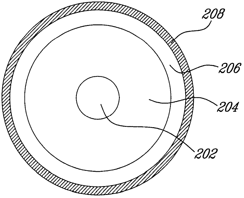
[0061] now give the basis figure 1 An example of a specific design of a two-stage brightness converter. It should be understood that the parameters of the converter specified below are given by way of example only, and that there are many other possible designs for such a two-stage luminance converter.

[0062] The first stage 102 of the brightness converter should be carefully designed to obtain lasing emission in the second optical wavelength band (ie between 1020 and 1030 nm). The first stage 102 should be designed to have a maximum gain spectral density in the second optical band for efficient lasing.

[0063] With strong population inversion within the DCOF 102 of the first stage 102, such efficient lasing in the second optical wavelength band (ie between 1020 and 1030 nm) is obtained. In order to obtain the desired strong population inversion, a short cavity and a large ratio of core diameter to inner cladding diameter are used in order to obtain a strong absorption of...


PUM


Abstract

There is provided a two-stage brightness converter. A first brightness conversion stage has a laser cavity having a first optical waveguide doped with an active ion defining a first optical band with optical absorption, a second optical band with optical absorption and optical gain, and a third optical band with optical gain. The first laser cavity is pumped with a pump power having a wavelength in the first optical band to generate an intermediate optical signal in the second optical band. A second brightness conversion stage which is in cascade with the first brightness conversion stage comprises a second optical waveguide doped with the same active ion. The second brightness conversion stage is pumped with the intermediate optical signal to obtain a high brightness optical signal in the third optical band.

Description

[0001] Cross References to Related Applications [0002] This application claims priority to US Provisional Application 61 / 146,812, filed January 23, 2009, the specification of which is incorporated herein by reference. technical field [0003] This specification relates to the generation of optical signals, and more specifically to brightness transformation. Background technique [0004] Today, fiber lasers are the most powerful solid-state laser technology due to their compactness, reliability, operating efficiency and their high output power levels. Fiber lasers can be viewed as single-stage brightness converters. [0005] One approach to designing brightness converters uses laser cavities (see e.g. "1.3kW Yb-doped fiber laser with excellent beam quality" by A. Liem et al. Proc. of CLEO 2004, CPDD2, Vol.2, pp.1067-1068 , (2004)). In such a brightness converter, a large number of multimode pump diodes are coupled into a rare earth-doped double-clad fiber (DCOF) using a ...

Claims


Application Information

Patent Timeline
Patent Type & Authority Applications(China)
IPC IPC(8): H01S3/067G02B6/036H01S3/0941
CPCH01S3/094007H01S3/0675H01S3/06716G02B6/036H01S3/09415H01S3/06729H01S3/094042H01S3/1618
Inventor J-N・马兰S・沙蒂格尼
Owner CORACTIVE HIGH TECH
Why Eureka
Try Eureka