
A method for reducing bandwidth of ir interface and distributed base station

A technology of interface bandwidth and interface, which is applied in the field of methods and distributed base stations, can solve problems such as low transmission efficiency, increased transmission network costs, and increased cost of Ir interface bandwidth requirements, achieving the effect of increasing the occupation ratio and reducing bandwidth requirements

Inactive Publication Date: 2011-12-21
POTEVIO INFORMATION TECH
View PDF4 Cites 45 Cited by
  • Summary
  • Abstract
  • Description
  • Claims
  • Application Information

AI Technical Summary

Problems solved by technology

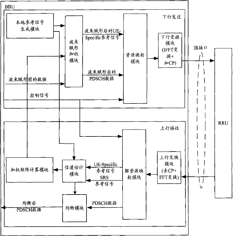
[0023] It can be seen from the above data that on the downlink transmitting side, the bandwidth required by the Ir interface after beamforming is doubled (increased by 4 times) compared to before beamforming, and the bandwidth efficiency of data transmission is greatly reduced (reduced to 20%, reduced by 4 times), resulting in a substantial increase in the cost of the transmission network
[0024] For the uplink receiving side, in order to estimate the user’s uplink channel for uplink equalization and downlink beamforming, the uplink receiving side also needs to use multi-antenna reception. For example, if downlink beamforming uses 8 antennas for transmission, then uplink reception also needs to use 8-antenna reception, so similar to the downlink, the bandwidth requirements of the uplink Ir interface will also increase exponentially, and the cost of the transmission network will increase significantly
[0025] It can be seen from the above that, due to the introduction of beamforming in the existing baseband remote system, the data bandwidth of the uplink and downlink Ir interfaces has increased several times, but the effective data has not increased, which has greatly increased the cost of the Ir interface bandwidth requirements, and the transmission The problem of low efficiency

Method used


Image

  • A method for reducing bandwidth of ir interface and distributed base station
  • A method for reducing bandwidth of ir interface and distributed base station
  • A method for reducing bandwidth of ir interface and distributed base station

Examples


Embodiment Construction

[0058] In order to make the object, technical solution and advantages of the present invention clearer, the present invention will be further described in detail below with reference to the accompanying drawings and examples.

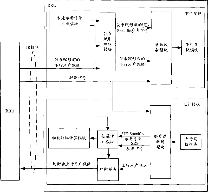
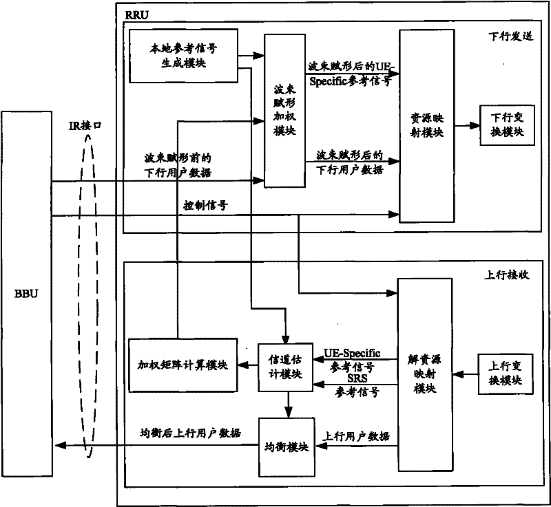
[0059] The main idea of ​​the present invention is: in the remote baseband system that introduces the beamforming function, the downlink beamforming related module and the uplink equalization processing related module are moved from the BBU to the RRU, so as not to increase the equipment BBU+RRU Under the premise of total cost and complexity, the bandwidth requirements of the uplink and downlink Ir interfaces are greatly reduced, thereby reducing the transmission cost of the Ir interface.

[0060] Based on above-mentioned main idea, the present invention provides a kind of method that reduces Ir interface bandwidth, and this method comprises:

[0061] During downlink transmission, the BBU sends downlink user data and downlink control signals before down...


PUM


Abstract

The present invention provides a method for reducing the bandwidth of an Ir interface, which is applied to a remote baseband system that introduces a beamforming function. The method includes: when sending downlink, the indoor baseband processing unit BBU transmits The downlink user data and downlink control signals are sent to the remote radio unit RRU, and the RRU performs downlink beamforming processing according to the downlink user data and downlink control signals; when receiving uplink, the BBU sends the uplink control signals to the RRU through the Ir interface , the RRU performs uplink equalization processing on the received uplink user data according to the uplink control signal, and sends the equalized uplink user data obtained after the uplink equalization processing to the BBU through the Ir interface. The present invention also provides a distributed base station corresponding to the above method. The application of the present invention can greatly reduce the bandwidth requirement of the Ir interface, and increase the effective data occupancy ratio of the Ir interface.

Description

technical field [0001] The invention relates to baseband remote system technology, in particular to a method for reducing Ir interface bandwidth and a distributed base station. Background technique [0002] In the 3G system, the baseband remote networking mode of BBU+RRU (indoor baseband processing unit + remote radio unit) has been applied on a large scale, and this networking mode will also be applied to LTE systems, TD-SCDMA systems, etc. . The baseband IQ signal is transmitted between the BBU and the RRU through an optical fiber. The interface between the BBU and the RRU is called an Ir interface. The bandwidth of the Ir interface depends on the transmission rate of the baseband signal. [0003] Taking the LTE system as an example, under the bandwidth of 20MHz, when the antenna configuration is 2×2 MIMO (Multiple Input Multiple Output), the Ir interface bandwidth of a single sector is calculated as follows: [0004] Ir interface bandwidth = 30.72MHz (sampling rate) × 1...

Claims


Application Information

Patent Timeline
IPC IPC(8): H04W88/08H04B7/15H04L25/02
Inventor 吴迪万建超
Owner POTEVIO INFORMATION TECH
Learn More