
Electromagnetic clamping device for mechanical milling head

A technology of clamping device and milling head, which is applied in positioning devices, metal processing mechanical parts, clamping and other directions to achieve the effects of improving processing accuracy, economical cost, and improving processing range and processing efficiency.

Inactive Publication Date: 2011-12-21
北京伊贝格机械有限公司
View PDF6 Cites 6 Cited by
  • Summary
  • Abstract
  • Description
  • Claims
  • Application Information

AI Technical Summary

Problems solved by technology

However, in the 714 or 715 vertical machining center machine tools without hydraulic oil, if you want to use a mechanical milling head that can be automatically indexed and replaced, you need to find other solutions, which is still a blank in the industry.

Method used


Image

  • Electromagnetic clamping device for mechanical milling head
  • Electromagnetic clamping device for mechanical milling head
  • Electromagnetic clamping device for mechanical milling head

Examples


Embodiment Construction

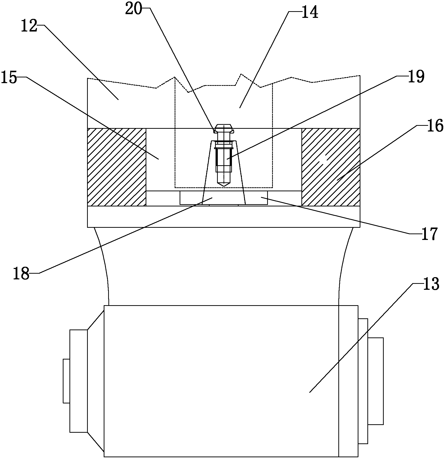
[0018] Such as Figure 3-4 As shown, an electromagnetic clamping device for a mechanical milling head described in the embodiment of the present invention includes a ram 12 and a mechanical milling head 13, the bottom of the ram 12 is provided with a protrusion 15, and the ram 12 and the protrusion The inside of 15 is provided with a main shaft 17, one end of the main shaft 17 is connected to the clamping system 14, the other end of the main shaft 17 is provided with a tapered handle 18, and the top of the tapered handle 18 is provided with a pull claw 20, and the bottom of the protrusion 15 is provided with a mechanical The top of the milling head 13 and the mechanical milling head 13 are provided with a pull stud 19 with an integrated structure, the pull stud 19 is fixed by the pull claw 20, and an electromagnet 16 positioned outside the protrusion 15 is arranged below the ram 12 .

[0019] During use, move upwards until the clamping system 14 clamps the pull stud 19 on the ...


PUM


Abstract

The invention relates to an electromagnetic clamping device for a mechanical milling head, comprising a ram and a mechanical milling head, a protrusion is provided at the bottom of the ram, a main shaft is provided inside the ram and the protrusion, and one end of the main shaft is connected and clamped. system, the other end of the main shaft is provided with a tapered handle, and the top of the tapered handle is provided with pulling claws. The mechanical milling head is provided under the protrusion, and the top of the mechanical milling head is provided with a pull stud integrated with it. The pull stud passes through the The pulling claw is fixed, and an electromagnet located outside the protrusion is arranged under the ram. The beneficial effects of the present invention are as follows: replace polluted hydraulic oil with non-polluting electric energy, and play the role of cleaning, environmental protection, green and low-carbon; the traditional vertical machining center can realize the vertical and horizontal conversion of the machining direction, which greatly improves the Improve the processing range and processing efficiency of the machine tool, realize multi-process processing in one clamping, and improve the processing accuracy of the product; compared with the high price of the oil cylinder system, the cost of the electromagnetic system is more economical, and it is more suitable for use on economical machining centers.

Description

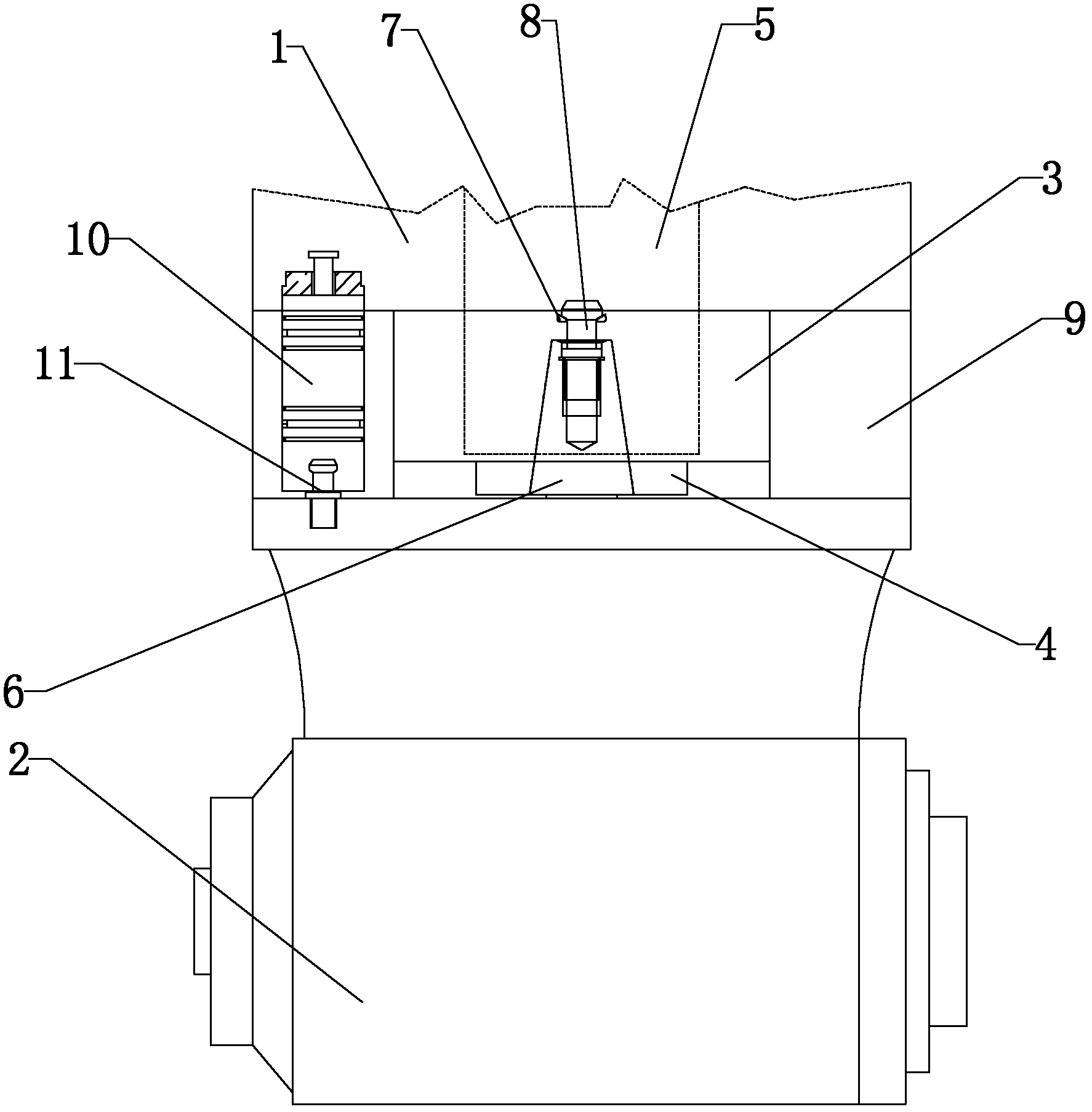
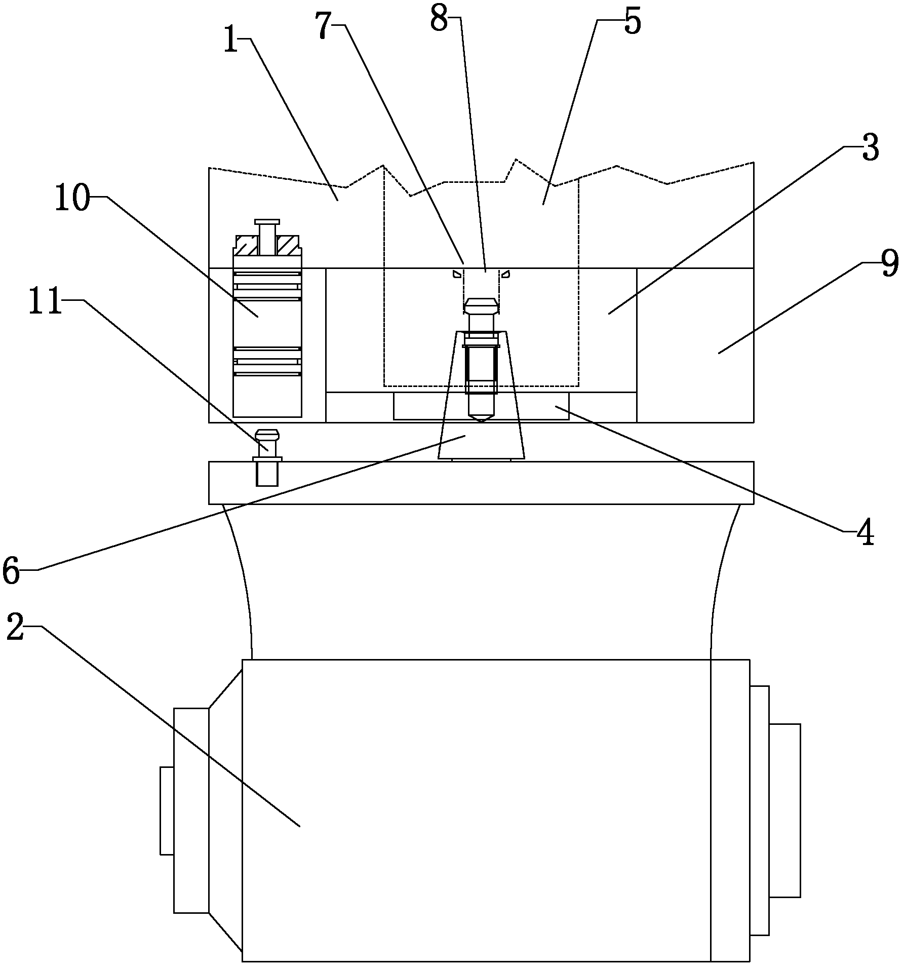
technical field [0001] The invention relates to the field of electric tools, in particular to an electromagnetic clamping device for a mechanical milling head. Background technique [0002] At present, the general-purpose mechanical milling head is usually connected to the machine tool ram in several ways: 1. Manual, which is the easiest way, but the efficiency is very low, and it is impossible to realize the automatic indexing of the mechanical milling head and different machine tools. Automatic replacement of milling head; 2. Oil cylinder + pull nail type, such as Figure 1-2 As shown, the structure includes a ram and a mechanical milling head 2 arranged under the ram 1, a protrusion 3 is provided at the bottom of the ram 1, a main shaft 4 is provided inside the ram 1 and the protrusion 3, and the main shaft 4 One end of the main shaft 4 is connected to the clamping system 5, the other end of the main shaft 4 is provided with a tapered handle 6, and the top of the tapered ...

Claims


Application Information

Patent Timeline
Patent Type & Authority Applications(China)
IPC IPC(8): B23C9/00B23Q3/155
Inventor 邵传伟
Owner 北京伊贝格机械有限公司
Learn More