
A quasi-distributed composite structure strain and temperature detection system

A composite material, quasi-distributed technology, used in thermometers, thermometers, measuring devices and other directions with physical/chemical changes, can solve the problems of large measurement errors, low signal-to-noise ratio, difficult remote monitoring, etc., to achieve convenient and feasible production. , The technological level is mature, the effect of prolonging the light time

Inactive Publication Date: 2011-12-07
DONGHUA UNIV
View PDF5 Cites 20 Cited by
  • Summary
  • Abstract
  • Description
  • Claims
  • Application Information

AI Technical Summary

Problems solved by technology

In the prior art, if a fiber grating is used to measure multiple points, a spectrometer is often used to measure the wavelength signal, so that the cost of wavelength signal demodulation is relatively high; and the number of measurement points is limited by the bandwidth of the light source; and when the light source When the output power is constant, the larger the number of measurement points, the lower the signal-to-noise ratio, resulting in larger measurement errors
Therefore, the current fiber grating point multi-parameter system is usually low in cost performance, difficult to realize remote monitoring and poor in repeatability. At the same time, a large amount of useless data needs to be screened during measurement, and the signal-to-noise ratio of the measurement is not high, which affects the accuracy of the measurement.

Method used


Image

  • A quasi-distributed composite structure strain and temperature detection system
  • A quasi-distributed composite structure strain and temperature detection system

Examples


Embodiment Construction

[0020] The present invention will be further explained below in conjunction with specific embodiments. It should be understood that these embodiments are only used to illustrate the present invention and not to limit the scope of the present invention. In addition, it should be understood that after reading the teachings of the present invention, those skilled in the art can make various changes or modifications to the present invention, and these equivalent forms also fall within the scope defined by the appended claims of this application.

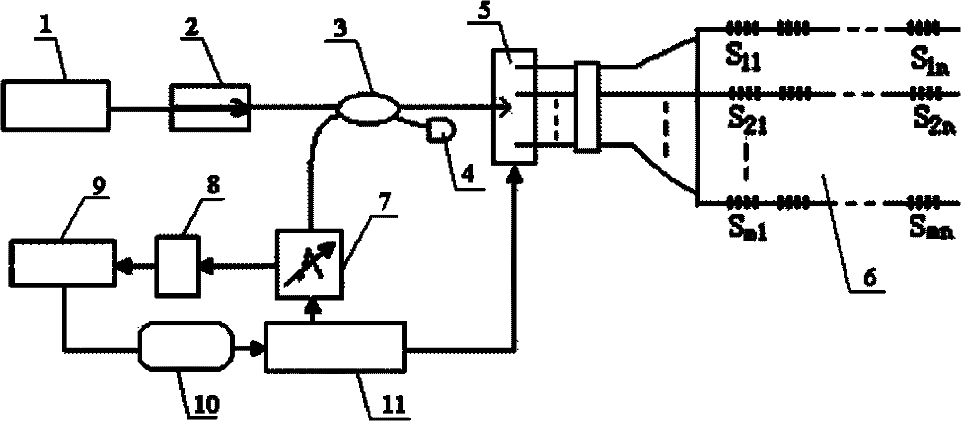
[0021] The embodiment of the present invention relates to a quasi-distributed composite material structure strain and temperature detection system, such as figure 1 As shown, including broadband light source 1, fiber isolator 2, 2×2 fiber coupler 3, index matching liquid 4, 1×m optical switch 5, m×n network fiber grating sensor head 6, fiber adjustable FP The filter 7, the photoelectric conversion module 8, the signal amplifier 9, the data ...


PUM


Abstract

The invention relates to a quasi-distributed composite structure strain and temperature detection system. Light output by a broadband light source passes through an optical fiber isolator and enters the input end of a 2*2 optical fiber coupler; the light output by the 2*2 optical fiber coupler enters the input end of a 1*m optical switch; the light output by the 1*m optical switch enters an m*n network type optical fiber grating sensing head; the light reflected by the m*n network type optical fiber grating sensing head sequentially passes through the 1*m optical switch and the 2*2 optical fiber coupler and further enters the input end of an optical fiber adjustable F-P (Fabry-Perot) filter; and the light output by the optical fiber adjustable F-P filter sequentially passes through a photoelectric conversion module, a signal amplifier, a data acquisition card and a computer, and the computer is used for processing and displaying data. The system utilizes the optical fiber adjustable F-P filter to realize wavelength demodulation of signal light reflected by all sensing optical fiber gratings, and has the advantages of anti-electromagnetic interference effect, all-optical fiber type measurement, a large number of multiplexing measuring points, remote monitoring, non-destructive measurement and the like.

Description

Technical field [0001] The invention relates to the technical field of optical fiber grating sensing, in particular to a quasi-distributed composite material structure strain and temperature detection system with multi-parameter measurement function and multi-point measurement function. Background technique [0002] Fiber grating is an optical element that establishes a certain spatial refractive index periodic distribution in the optical fiber, so that the propagation characteristics of light can be changed. Fiber grating is an optical element that establishes a certain spatial refractive index periodic distribution in the optical fiber, so that the propagation characteristics of light can be changed. When broadband light is incident on the fiber Bragg grating, the center wavelength of the reflected light (Brague wavelength) λ B , Given by Bragg's equation: λ B = 2nΛ [0003] Among them, n is the effective refractive index of the core, and Λ is the grating period. Since the meas...

Claims


Application Information

Patent Timeline
Patent Type & Authority Applications(China)
IPC IPC(8): G01B11/16G01K11/32G01K11/3206
Inventor 詹亚歌罗君吴华余木火
Owner DONGHUA UNIV
Learn More