Exhaust cleaner for internal combustion engine
A technology for exhaust purification devices and internal combustion engines, which is applied to exhaust devices, internal combustion piston engines, noise reduction devices, etc., and can solve problems such as deterioration of fuel efficiency of internal combustion engines
- Summary
- Abstract
- Description
- Claims
- Application Information
AI Technical Summary
Problems solved by technology
Method used
Image
Examples
Embodiment approach 1
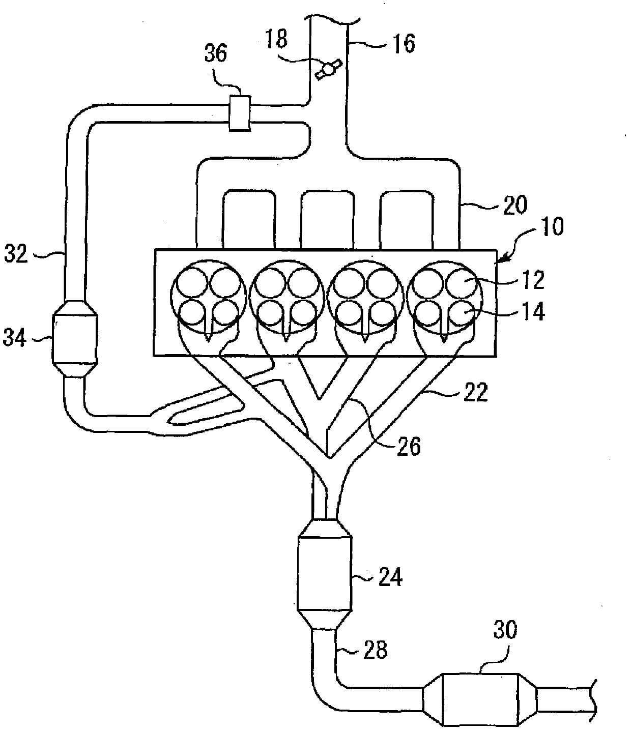
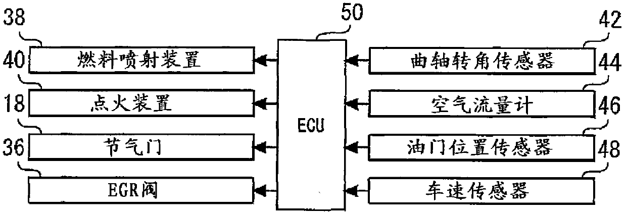
[0042] figure 1 It is a figure which shows the internal combustion engine in Embodiment 1 of this invention. figure 1 The illustrated internal combustion engine 10 is used as a power source of a vehicle or the like. The internal combustion engine 10 of the present embodiment is a spark ignition type internal combustion engine provided with a fuel injector (not shown) that directly injects fuel into a cylinder. This internal combustion engine 10 is of a series 4-cylinder type. However, in the present invention, the number of cylinders and the arrangement of cylinders are not particularly limited. Two intake valves 12 and two exhaust valves 14 are provided in each cylinder.
[0043] An intake pipe 16 is connected to the internal combustion engine 10 . On the way of the intake pipe 16, a throttle valve 18 for controlling the amount of intake air is provided. Intake gas supplied from the intake pipe 16 is distributed by the intake manifold 20 and flows into the cylinders.
...
Embodiment approach 2
[0075] Next, refer to Image 6 , Embodiment 2 of the present invention will be described, but the description will focus on the points of difference from Embodiment 1 described above, and descriptions of the same items will be simplified or omitted. Using the same hardware configuration as the above-mentioned Embodiment 1, instead of Figure 4 Shown program, make ECU50 carry out the Image 6 The program shown in this example implements this embodiment.
[0076] In the first embodiment described above, whether or not the amount of PM flowing into the catalyst is greater than the second threshold β is determined based on the presence or absence of acceleration, but in this embodiment, the number of PM particles in the engine exhaust gas is directly compared with the second threshold β.
[0077] Image 6 It is a flowchart of a program executed by ECU 50 in the present embodiment to realize the above-mentioned functions. according to Image 6 The shown routine first estimates...
Embodiment approach 3
[0084] Next, refer to Figure 7 , Embodiment 3 of the present invention will be described, but the description will focus on the points of difference from Embodiments 1 and 2 described above, and descriptions of the same items will be simplified or omitted.
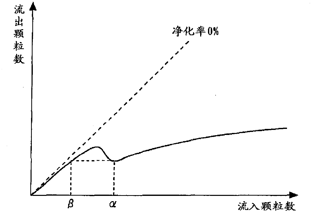
[0085] As mentioned above, the catalytic converter that combusts PM is expressed as image 3 characteristics as shown. That is, in the graph showing the relationship between the amount of PM flowing into the catalyst and the amount of PM flowing out of the catalyst, there is a portion where the amount of PM flowing out of the catalyst decreases as the amount of PM flowing into the catalyst increases.
[0086] However, according to the findings of the inventors of the present invention, in the region where the space velocity SV of the catalytic converter is somewhat large, the image 3 characteristics as shown. That is, in a region where the space velocity SV of the catalytic converter is to a certain extent, the charac...
PUM
 Abstract
Description
Claims
Application Information
 - R&D
- Intellectual Property
- Life Sciences
- Materials
- Tech Scout
- Unparalleled Data Quality
- Higher Quality Content
- 60% Fewer Hallucinations
Browse by: Latest US Patents, China's latest patents, Technical Efficacy Thesaurus, Application Domain, Technology Topic, Popular Technical Reports.
© 2025 PatSnap. All rights reserved.Legal|Privacy policy|Modern Slavery Act Transparency Statement|Sitemap|About US| Contact US: help@patsnap.com


