High thermal efficiency steam generating device for caring products

A technology of steam generating device and nursing product, which is applied in steam generation, steam generation method, layered products, etc., can solve the problems of long heating time (more than 2 minutes, difficult to clean, large volume and space, etc., to achieve easy assembly and The effect of post-cleaning and maintenance, no leakage, safety and reliability, and high degree of modularity

Inactive Publication Date: 2011-11-23
MIDEA GRP CO LTD
View PDF9 Cites 10 Cited by
  • Summary
  • Abstract
  • Description
  • Claims
  • Application Information

AI Technical Summary

Problems solved by technology

To sum up, the disadvantages of the traditional heating wire heating technology are: large volume and space occupation, low efficiency of indirect repeated heating, not easy to clean, easy to break and easy to spark, and the life of the heating wire is about one year
[0003] The core heating components of existing steam products all use heating cores made of die-casting heating pipes in aluminum alloys, such as the built-in steam generator of the garment steamer disclosed in Chinese patent ZL200920160371.0, and the heating pipe 201 does not generate heat In the body 200, in this way, the heat radiation generated by the heating wire must penetrate the insulating and heat-conducting filler, the metal outer tube, and the die-casting aluminum material, and finally can be transferred to the liquid water in the hot pot. During this period, the heat radiation loss accounts for about 40%. %, its heating efficiency is only less than 60%. The shortcomings of the product are that the heating time is too long (more than 2 minutes), the thermal efficiency is low, and the life of the product hot pot is short (less than two years).

Method used


Image

  • High thermal efficiency steam generating device for caring products
  • High thermal efficiency steam generating device for caring products
  • High thermal efficiency steam generating device for caring products

Examples


Embodiment Construction

[0020] The specific implementation manners of the present invention will be further described below in conjunction with the drawings and examples.

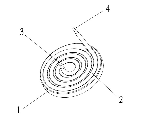
[0021] Such as Figures 1 to 5 As shown, the structure of the thick film heating element 1 involved in the patent of the present invention is divided into: a base 11 made of but not limited to stainless steel or ceramic materials; an insulating layer 12 made of insulating materials; Printed heating resistor layer 13; protective layer 14 made of materials with insulation and good thermal conductivity. The vaporization pipe 2 is closely attached to the base 11 and integrated with the heating element 1 . After the heating element 1 is energized, the heating resistor works to generate heat, which is transferred to the vaporization pipe 2 through the protective layer 14 .

[0022] Liquid water flows into the vaporization pipe 2 through the water inlet 3 of the vaporization pipe 2, absorbs the heat generated by the heating element 1 a...


PUM


Abstract

The invention provides a high thermal efficiency steam generating device for caring products. The steam generating device at least comprises a heating element and a vaporization duct; the vaporization duct is provided with a water inlet and a steam outlet; the heating element is a thick film heating element; and the vaporization duct is regularly and fixedly arranged on the thick film heating element to form a whole. A heating plate made of the thick film heating element and the vaporization duct connected with the heating plate are adopted in the steam generating device, the vaporization duct is provided with the water inlet and the steam outlet, and the vaporization duct is fixedly connected with the heating plate, so that reliable connection between the vaporization duct and the heating plate is ensured and the heating surface is uniform. Therefore, the advantages of long service life of the thick film heating element, extremely high heating efficiency, high reliability of the product, convenience for cleaning and maintenance and the like are fully exerted; and the defects of short service life, low heating efficiency, heavy weight, inconvenience for cleaning and maintenance and the like of the conventional steam hot pot products are radically overcome.

Description

technical field [0001] The invention relates to a steam generating device, in particular to a steam generating device suitable for care products such as garment irons, irons, steam cleaners, and steam sterilizers. Background technique [0002] The working principle of the traditional heating wire is the same as that of other metal heating elements, which is the electric heating phenomenon after the metal is energized. Electric heating means that after the current passes through the conductor, the current will generate a certain amount of heat and be transmitted by the conductor. The heating wire itself is a metal conductor, which will emit heat and provide heat energy after being energized. In order to solve the shortcoming that the heating wire is easy to oxidize (especially under high temperature working conditions), it is necessary to add anti-oxidation elements to the heating wire material, which not only increases the difficulty of the manufacturing process, but also g...

Claims


Application Information

Patent Timeline
Patent Type & Authority Applications(China)
IPC IPC(8): F22B1/28B32B3/22B32B9/04
Inventor 刘宇忠梁朝华李峥
Owner MIDEA GRP CO LTD
Why Eureka
Try Eureka