
Method and network equipment for forwarding multicast streaming

A technology of network equipment and multicast forwarding table, which is applied in the field of network communication and can solve the problems of inability to realize accurate forwarding of multicast streams, inability to distinguish VLANs, and inability to know the delivery.

Active Publication Date: 2011-11-16
BEIJING XINWANG RUIJIE NETWORK TECH CO LTD
View PDF6 Cites 8 Cited by
  • Summary
  • Abstract
  • Description
  • Claims
  • Application Information

AI Technical Summary

Problems solved by technology

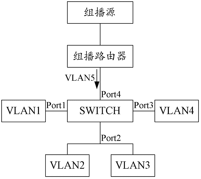
[0004] When performing multicast stream forwarding in the Super VLAN according to the above method, since the member interfaces in the Sub VLAN are simply converted into member interfaces of the Super VLAN, the information recorded in the multicast forwarding entry is only the Super VLAN port information, that is, The entire multicast forwarding table entry is still hung on the Super VLAN, so when a physical interface of the Super VLAN belongs to multiple Sub VLANs at the same time, it is impossible to know the specific delivery of the multicast stream to the physical interface when delivering the multicast stream. Which Sub VLAN under the interface
[0005] In a network architecture composed of multiple ordinary VLANs, the above problems may also exist, that is, when multiple VLANs share a port, it will not be possible to distinguish the specific VLAN that requests the multicast stream when forwarding the multicast stream. The multicast stream will be forwarded to all VLANs connected through the physical interface, and precise forwarding of the multicast stream cannot be achieved

Method used


Image

  • Method and network equipment for forwarding multicast streaming
  • Method and network equipment for forwarding multicast streaming
  • Method and network equipment for forwarding multicast streaming

Examples


Embodiment 1

[0024] figure 1 It is a schematic flowchart of the method for forwarding a multicast stream according to Embodiment 1 of the present invention. like figure 1 As shown, the multicast flow forwarding method includes the following steps:

[0025] Step S101, configuring the upstream multicast inflow VLAN and the downstream multicast flow reception VLAN of the network device;

[0026] Step S102, when the network device receives a multicast join request message sent by a user of the downstream multicast stream VLAN from the port of the downstream multicast stream receiving VLAN, establish a group according to the multicast join request message and the port broadcast forwarding entry, wherein, the multicast join request message carries a user VLAN identifier for identifying the VLAN where the user is located and a multicast group identifier requested by the user, and the multicast forwarding entry includes the User VLAN identifier, said port and said multicast group identifier;

...

Embodiment 2

[0036] On the basis of the multicast flow forwarding method in the first embodiment above, the downstream multicast flow receiving VLAN includes a plurality of sub-virtual local area network Sub VLANs of the super virtual local area network Super VLAN; correspondingly, the multicast join request message carried The user VLAN ID is a user Sub VLAN ID for identifying the Sub VLAN in which the user is located, and the multicast forwarding entry includes the user Sub VLAN ID, the port, and the multicast group ID.

[0037] image 3 It is a network architecture diagram applying the multicast flow forwarding method according to Embodiment 2 of the present invention. exist image 3 In the shown network, the Super VLAN includes two Sub VLANs, that is, Sub VLAN1 and Sub VLAN2. Among them, the IGMP Snooping function is enabled on the Sub VLAN1 of the Super VLAN, and then acts on the Sub VLAN1 alone; the multicast forwarding table entry is established on the Sub VLAN1, and the entrance ...

Embodiment 3

[0045] On the basis of the multicast stream forwarding method in the first embodiment above, the downstream multicast stream receiving VLAN includes a plurality of sub-virtual local area network Sub VLANs of the Super VLAN; correspondingly, the user The VLAN identifier includes the user Sub VLAN identifier for identifying the Sub VLAN where the user is located and the user Super VLAN identifier for identifying the Super VLAN where the user is located, and the multicast forwarding entry includes the user Super VLAN identifier, the user Sub VLAN identifier, said port and said multicast group identifier.

[0046] The multicast flow forwarding method of this embodiment can be applied to image 3 The network architecture shown in , but where the IGMP Snooping function is enabled on the Super VLAN, it controls the multicast forwarding behavior of the Super VLAN and the Sub VLAN of the Super VLAN. At this time, the multicast data flow is sent through the super VLAN through the Layer...


PUM


Abstract

The invention provides a method and network equipment for forwarding multicast streaming. The method comprises the following steps that: an upstream multicast streaming inflow virtual local area network (VLAN) and a downstream multicast streaming receiving VLAN of the network equipment are configured; when the network equipment receives a multicast joining request message, sent by a user of the downstream multicast streaming VLAN, from a port of the downstream multicast streaming receiving VLAN, the network equipment builds a multicast forwarding table entry according to the multicast joining request message and the port, wherein the multicast joining request message carries a VLAN identification which is used for identifying the VLAN of the user and a multicast group identification which is requested by the user, and the multicast forwarding table entry comprises the VLAN identification of the user, the port and the multicast group identification; and the network equipment receives the multicast streaming which is sent by a multicast streaming inflow VLAN and is corresponding to the multicast group identification, and the network equipment forwards the multicast streaming to the VLAN of the user according to the multicast forwarding table entry. The method and network equipment provided by the invention can realize accurate forwarding of the multicast streaming.

Description

technical field [0001] The invention relates to network communication technology, in particular to a multicast stream forwarding method and network equipment. Background technique [0002] Super Virtual Local Area Network (Super Virtual Local Area Network, Super VLAN) is a way of VLAN division and a management technology specially optimized for IP addresses. The principle is to assign the IP of a network segment to different sub-VLANs (Sub VLANs). Each Sub-VLAN is an independent broadcast domain, and different Sub-VLANs are isolated from each other on the second layer. When users in the Sub VLAN need to communicate at Layer 3, the IP address of the virtual interface of the Super VLAN is used as the gateway address, so that multiple VLANs share one IP address, thereby saving IP address resources. Super VLAN is widely used because of its beneficial effect. [0003] When multicast stream forwarding is performed on the Super VLAN, when the physical interface on the Sub VLAN re...

Claims


Application Information

Patent Timeline
Patent Type & Authority Applications(China)
IPC IPC(8): H04L12/18H04L12/46
Inventor 董吉华
Owner BEIJING XINWANG RUIJIE NETWORK TECH CO LTD
Learn More