
Energy-saving rotary stirring die box of wire drawing machine

A technology of rotary stirring and wire drawing machine, which is applied in the direction of wire drawing die, etc., can solve the problems of shortened service life of wire drawing die, increased die consumption, uncertainty, etc., and achieves reliable lubrication effect, extended service life and uniform wear

Inactive Publication Date: 2011-11-16
WUXI CHANGXIN TECH
View PDF8 Cites 13 Cited by
  • Summary
  • Abstract
  • Description
  • Claims
  • Application Information

AI Technical Summary

Problems solved by technology

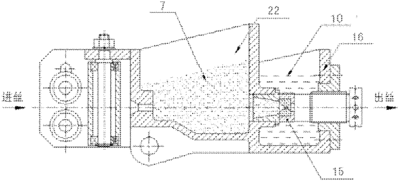
The mold box of the wire drawing machine has the following defects: 1. The lubricating powder is easy to coke at the conical hole of the wire drawing die inlet, thereby scraping off the lubricating carrier (coating) on ​​the surface of the steel wire, preventing the steel wire from carrying powder, resulting in lubrication failure, resulting in bright wire and shrinkage. 2. When used in the rough drawing (billet opening) machine, due to the irregularity of the cross-sectional geometry such as the diameter and roundness of the hot-rolled disc, the drawing die will wear unevenly, so that the geometric size of the drawn steel wire will be affected. 3. Driven by the steel wire, the lubricating powder is continuously piled forward, so that the steel wire behind is exposed without powder coverage, which affects the lubrication effect, and the lubricating powder needs to be manually regularly Stir evenly, making the product quality unstable and uncertain

Method used


Image

  • Energy-saving rotary stirring die box of wire drawing machine
  • Energy-saving rotary stirring die box of wire drawing machine
  • Energy-saving rotary stirring die box of wire drawing machine

Examples


Embodiment Construction

[0019] The specific embodiments of the present invention will be further described below in conjunction with the accompanying drawings.

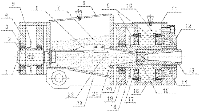
[0020] Figure 1~Figure 3 Among them, it includes wire inlet 1, stirring shaft 2, first bearing 3, first bearing seat 4, first sprocket 5, stirring rod 6, lubricating powder 7, lubricating box top cover 8, sealing ring 9, cooling water 10. Mold box body top cover 11, second bearing seat 12, top wire 13, second bearing 14, wire drawing die 15, mold box body 16, hollow shaft 17, second sprocket 18, third bearing 19, third Bearing block 20, lubricating taper hole 21, lubricating box body 22, blade 23, the 3rd sprocket 24, reduction motor 25, clutch 26, the 4th sprocket 27 etc.

[0021] Such as figure 2 , image 3 As shown, the present invention is an energy-saving rotary stirring mold box for a wire drawing machine, including a lubricating box body 22 and a mold box body 16 . Lubricating box body 22 is the container of a top opening, and l...


PUM


Abstract

The invention relates to an energy-saving rotary stirring die box of a wire drawing machine. The energy-saving rotary stirring die box comprises a lubrication box body and a die box body, wherein a wire drawing die is arranged in the die box body; a stirring device is arranged on the lubrication box body; a wire drawing die rotating device is arranged on the die box body; the stirring device and the wire drawing die rotating device share one double-output-shaft speed reduction motor; and clutches are arranged on the output shafts of the speed reduction motor. In the energy-saving rotary stirring die box, the stirring device arranged on the lubrication box body is used for stirring lubrication powder; as the lubrication powder cannot be accumulated in the lubrication box body, the lubrication effect is reliable; the wire drawing die rotating device arranged on the die box body can drive the wire drawing die to rotate, so that the wire drawing die is abraded uniformly, the service life of the wire drawing die can be prolonged, and the size of a drawn steel wire can be stabilized; and the stirring device and the wire drawing die rotating device share one double-output-shaft speed reduction motor, so that the energy-saving rotary stirring die box is compact in structure, low in cost and energy-saving.

Description

technical field [0001] The invention relates to a mold box of a wire drawing machine, in particular to an energy-saving rotary stirring mold box of a wire drawing machine. Background technique [0002] The metal wire drawing machine belongs to the pre-processing equipment for the production of metal products. Its function is to draw the wire or bar through the wire drawing machine, so that the diameter, roundness, internal metallographic structure, surface finish and straightness of the wire or bar are all improved. Meet the requirements. The wire drawing machine mold box is used to fix the wire drawing die and provide lubricating powder. [0003] Such as figure 1 As shown, it is a commonly used dry-type wire drawing machine mold box at present, which includes a lubricating box body 22 and a mold box body 16. Lubricating powder 7 is housed in the lubricating box body 22, cooling water 10 is housed in the mold box body 16, and the wire drawing die 15 is installed in the mo...

Claims


Application Information

Patent Timeline
Patent Type & Authority Applications(China)
IPC IPC(8): B21C3/14
Inventor 庄鸣裴友清
Owner WUXI CHANGXIN TECH
Learn More