A Measuring Cell for Optically Addressable Potential Sensors

A potential sensor and measuring cell technology, applied in the field of sensors, can solve problems such as complex design structure, bulky size, and insufficient accuracy, and achieve the effects of simple manufacturing process, high signal strength, and high sensitivity

Active Publication Date: 2016-12-14
GUILIN UNIV OF ELECTRONIC TECH
View PDF6 Cites 0 Cited by
  • Summary
  • Abstract
  • Description
  • Claims
  • Application Information

AI Technical Summary

Problems solved by technology

[0003] The development of the sensitive film of the optical addressable potential sensor is a hot spot at present, but there are few studies on the structure of the measurement cell of the optical addressable potential sensor
The existing optical addressable potential sensor measuring cell has a complex design structure, cumbersome control, and huge peripheral instruments, which is not conducive to system integration and productization
In the article "Research on Optical Addressing Potential Sensor Measurement System" in the 12th issue of "Instrument Technology and Sensors" in 2003, Niu Wencheng and others proposed to use a stepper motor as the power to drive the precision screw to rotate through the toothed belt to control the LED. The position change comes from optical addressing. This method is not accurate enough, and the product is bulky and inconvenient to operate, which increases the workload.
In the article "Application of Light-addressable Potential Sensors in Organophosphorus Detection" in the 10th issue of "Sensor Technology" in 2003, Xu Lei and others proposed the structure of integrating the LED array inside the test system. The manufacturing process of the sensor requires high requirements, and the replacement of the sensitive film and LED is very inconvenient

Method used


Image

  • A Measuring Cell for Optically Addressable Potential Sensors
  • A Measuring Cell for Optically Addressable Potential Sensors
  • A Measuring Cell for Optically Addressable Potential Sensors

Examples


Embodiment Construction

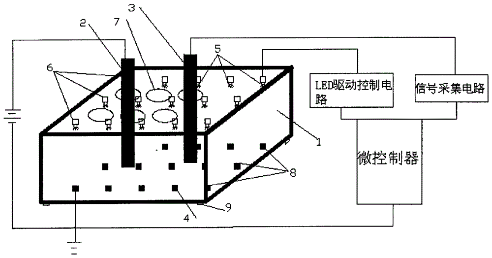
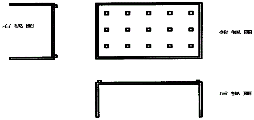
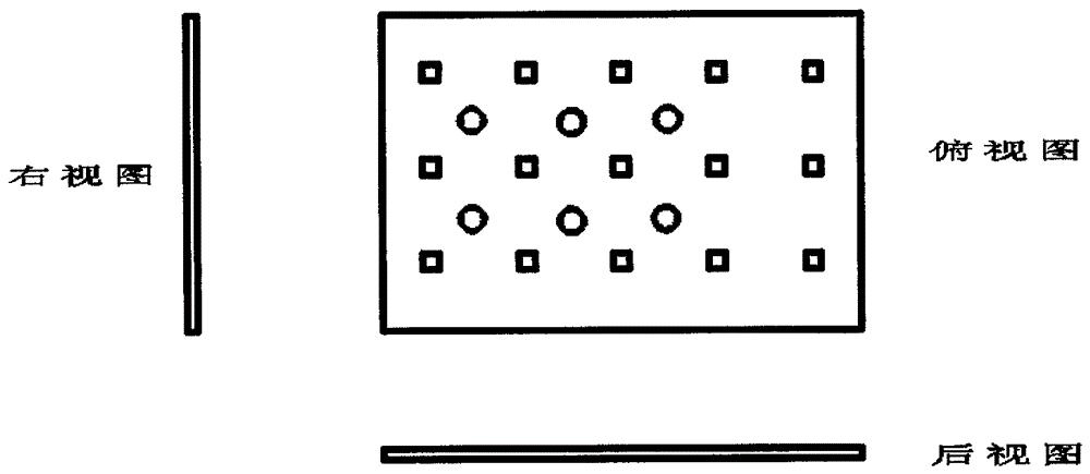
[0013] Embodiments of the present invention will be specifically described below in conjunction with the accompanying drawings. figure 1 It is the structural diagram of the photo-addressable potential sensor, including measuring cell (1), reference electrode (2), measuring electrode (3), silicon wafer coated with sensitive film (4), LED array (5), square array ( 6), circular holes (7), square arrays (8), brackets (9) and other components. The LED array (5) is embedded in the square array (6); the silicon chip (4) of the sensitive film is adhered to the bottom of the square array (8); the reference electrode (2), the measuring electrode (3) are inserted into the circular hole (7), Immersed in the solution to be tested; a bias voltage is applied between the bottom of the silicon chip and the reference electrode (2); the whole optical addressing potential sensor structure is supported by the support (9); the photocurrent is drawn out by the measuring electrode (3). Figure 4 It ...


PUM


Abstract

The invention discloses a measuring pool for an optical addressing potential sensor, which is composed of a square array (6), a round hole (7) and a square array (8), and the square arrays (6) are arranged at equal intervals on the top of the measuring pool (1) On the cover, the square arrays (8) are arranged at the bottom of the measuring pool at equal intervals, and are aligned up and down with the square arrays on the top cover, in one-to-one correspondence; the solution can be multi-parameterized and multi-parameterized by coating different sensitive films on the silicon wafer. Point measurement can also be applied to the measurement of the concentration distribution of the same solution component in different measurement domains. The overall structure is a standard cuboid, which is simpler in structure than the method of controlling the number of steps of the stepping motor, accurate in addressing, easy to integrate, and easy to operate. The invention solves the disadvantages of complicated peripheral control and manufacturing process, cumbersome operation and inaccurate addressing in the existing optical addressing sensor measuring pool.

Description

technical field [0001] The invention belongs to the field of sensors, and in particular relates to a measuring pool for an optical addressing potential sensor. Background technique [0002] Light Addressable Potentionmetric Sensor (LAPS) is a biochemical sensor using the principle of semiconductor field effect, which has important research and application value in biochemistry, medicine and other fields. Because of its characteristics of multi-parameter measurement, small size, good stability, easy packaging, high sensitivity, and short detection time, it has attracted extensive research and application. Optically addressable potential sensors can be classified into a MIS (metal / insulator / semiconductor) structure and an EIS (electrolyte solution / insulator / semiconductor) structure. The measuring cell is used to realize the EIS structure of the light-addressable potentiometric sensor, which is used to detect the concentration of specific ions in the solution. By applying a b...

Claims


Application Information

Patent Timeline
Patent Type & Authority Patents(China)
IPC IPC(8): G01N27/414
Inventor 陈真诚梁晋涛赵宏田蒋行国胡寒冬
Owner GUILIN UNIV OF ELECTRONIC TECH
Why Eureka
Try Eureka