
Pneumatic actuator, and system and method for controlling same

A technology for pneumatic actuators and sensors, applied in computer programs and computer program products, systems for controlling the pneumatic actuators, motor vehicles, and the fields of controlling pneumatic actuators, which can solve the problems of limited piston speed and achieve the effect of easy programming

Inactive Publication Date: 2011-10-26
SCANIA CV AB
View PDF4 Cites 9 Cited by
  • Summary
  • Abstract
  • Description
  • Claims
  • Application Information

AI Technical Summary

Problems solved by technology

This has the disadvantage that the speed of the piston going through the stroke is limited, and this is essentially only necessary in the middle or end of the stroke

Method used


Image

  • Pneumatic actuator, and system and method for controlling same
  • Pneumatic actuator, and system and method for controlling same
  • Pneumatic actuator, and system and method for controlling same

Examples


Embodiment Construction

[0037]Herein, the term "link" refers to a communication link, which may be a physical line such as an optical communication line, or a non-physical line such as a wireless connection, for example, a radio or microwave link, and the like.

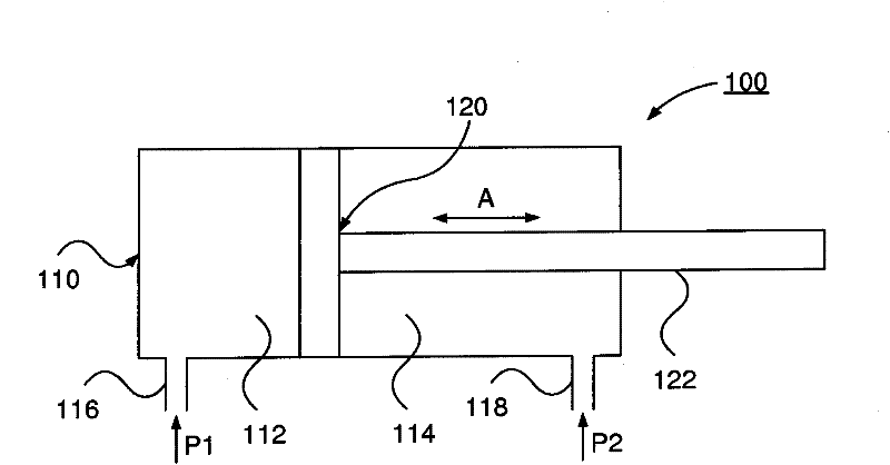
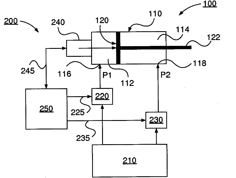
[0038] figure 1 A pneumatic actuator 100 according to an embodiment of the present invention is schematically shown.

[0039] The pneumatic actuator 100 includes a cylinder 110 and a piston 120 arranged to reciprocate within the cylinder 110 . The piston 120 divides the cylinder 110 into a first space 112 and a second space 114 . The cylinder includes a first port 116 , channel 116 or opening 116 for communicating a first gaseous medium (eg, air, etc.) into and / or out of the first space 112 . The cylinder also includes a second port 118 , channel 118 or opening 118 for communicating a second gaseous medium (eg, air, etc.) into and / or out of the second space 114 .

[0040] According to the invention, said first gaseous medium is arranged t...


PUM


Abstract

The present invention relates to a pneumatic actuator comprising a cylinder and a piston arranged to reciprocate within said cylinder, said piston dividing said cylinder into a first space having a first port for passing a first gaseous medium into said first space, and a second space having a second port for passing a second gaseous medium into said second space, so as to move said piston, wherein said first gaseous medium is arranged to be provided as a first set of pulses, and said second gaseous medium is arranged to be provided as a second set of pulses, said sets being arranged to provide an impact difference for moving said piston, and at least one position sensor arranged at said pneumatic actuator to sense the position of the piston, said control of the pneumatic actuator being based upon the position of the piston. The present invention also relates to a system for controlling a pneumatic actuator. The present invention also relates to a method for controlling a pneumatic actuator. The present invention also relates to a computer program and a computer program product.

Description

technical field [0001] The invention relates to a pneumatic actuator according to the preamble of claim 1 . The invention also relates to a system for controlling the pneumatic actuator according to the preamble of claim 7 . The invention also relates to motor vehicles. The invention also relates to a method for controlling a pneumatic actuator according to the preamble of claim 9 . The invention also relates to computer programs and computer program products. Background technique [0002] Pneumatic actuators or cylinders are used in many applications. For example, pneumatic actuators are used to control gear shifts in gearboxes of motor vehicles. Such a pneumatic actuator comprises a cylinder in which a piston is arranged for reciprocating movement, the piston being arranged to drive the shifting of the transmission by stroke. The piston divides the cylinder into a first space and a second space. The piston is reciprocated by introducing compressed air from the air va...

Claims


Application Information

Patent Timeline
IPC IPC(8): F15B11/046F15B11/042F15B11/04F15B11/048
CPCF15B11/06F15B21/087F15B2211/3057F15B2211/30575F15B2211/328F15B2211/6336F15B2211/6653F15B2211/6656F15B2211/7053F15B2211/75F15B2211/8855F16H61/30
Inventor O·施吕特J·努德奎斯特
Owner SCANIA CV AB
Learn More