
Rotary swaging forming equipment

A technology of forming equipment and forging die, which is applied in the advanced field of material forming, can solve the problems of small impact acceleration of the workpiece, large forging length, no diameter changing function, etc., achieve reasonable axial force and forging force, and reduce impact and wear, the effect of easy automation control

Active Publication Date: 2012-11-07
XI AN JIAOTONG UNIV
View PDF0 Cites 0 Cited by
  • Summary
  • Abstract
  • Description
  • Claims
  • Application Information

AI Technical Summary

Problems solved by technology

At present, the curved surface of the forging hammer in the rotary forging equipment is usually a curved surface with the law of parabola or cosine acceleration, and there is a single point contact between the curved surface of the forging hammer and the roller. The acceleration continuity is poor during contact, and the impact on the roller is large, which causes the vibration and noise of the whole equipment, but the impact acceleration on the workpiece is small, the impact time is long, the impact strength is small, the efficiency is low, and the forming accuracy is poor.
[0005] The current rotary forging equipment usually does not have the function of changing the diameter. If it has the function of changing the diameter, it is also a hydraulically driven diameter changing mechanism. This type of diameter changing mechanism is complex in structure, poor in real-time performance, and inconvenient to operate. Leading to poor forming accuracy of the workpiece, high scrap rate and low efficiency
[0006] At the same time, the forging die structure in the rotary forging forming equipment also plays a key role in the forming of the workpiece. If the structure of the necking area and the working area in the forging die structure are not reasonable enough, it will result in poor forming quality and low efficiency of the workpiece.
Because the working area is too long, that is, the forging length is large, the corresponding forging energy is increased; the working area is too short, the required forging force and energy are small, but the straightness and smoothness of the outer surface of the workpiece are poor

Method used


Image

  • Rotary swaging forming equipment
  • Rotary swaging forming equipment
  • Rotary swaging forming equipment

Examples


Embodiment Construction

[0033] The present invention will be described in detail below in conjunction with the accompanying drawings.

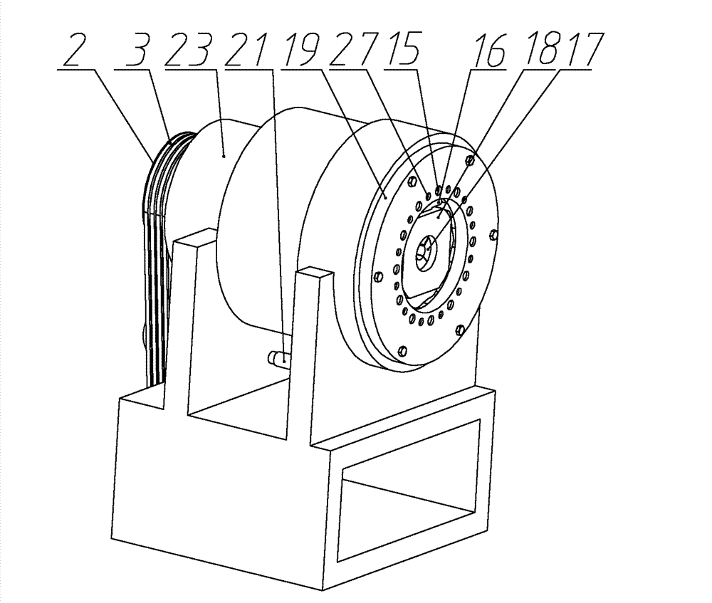
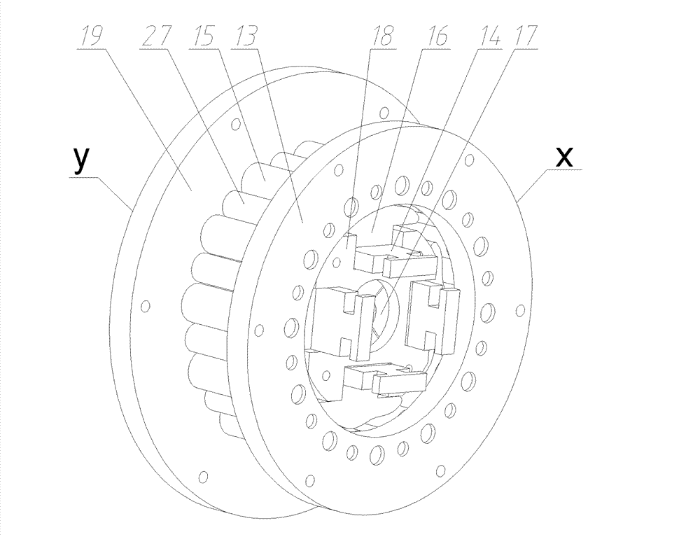
[0034] refer to figure 1 with figure 2 , a swaging forming equipment, comprising a swaging mechanism and a variable diameter mechanism, the swaging mechanism, the variable diameter mechanism, and the swaging main shaft 6 are sequentially arranged in the through hole above the main swaging main base 23, and the swaging main shaft 6 is installed in the front and rear Two deep groove ball bearings 5 ​​of the layout are driven by the swaging main motor 24 through the large pulley 2, the belt 3 and the small pulley 26. The two deep groove ball bearings 5 ​​are installed in the swaging main frame 23 through In the hole, the swaging main motor 24 is installed on the bottom of the swaging main base 23, the swaging main shaft 6 is connected with the variable diameter mechanism connecting frame 8 in the variable diameter mechanism through the transition plate 7, and the vari...


PUM


Abstract

The invention discloses a rotary swaging forming equipment, which comprises a rotary swaging mechanism and a diameter changing mechanism, wherein the rotary swaging mechanism is fixed with a rotary swaging main base through left and right pin roller mounting disks; a rotary swaging spindle is connected with a diameter changing mechanism connecting frame and a turntable respectively; forging hammers are matched with a chute in the turntable; for the curved surfaces of the forging hammers, a four symmetrical cycloid rule and a multi-point contact design are adopted; auxiliary pin rollers matched with the curved surfaces of the forging hammers are arranged between main pin rollers uniformly distributed along the circumferential direction of the rotary swaging spindle; wedge-shaped blocks in the diameter changing mechanism are matched with a chute on the end part of a wedge-shaped block slide disk; left and right lug bosses on a diameter changing mechanism pushing disk are matched with a guide rail groove on the rotary swaging main base; the diameter changing mechanism is driven by a servomotor and a ballscrew nut fitting; by designing the sizes of a neck reducing area of a forging die, a transitional fillet and a hammering work area, a workpiece is reasonably hammered. The impact of the forging hammers on the equipment during rotary swaging is reduced, the vibration and noise of the equipment are reduced, high-precision real-time diameter changing hammering can be realized, and the equipment has the advantages of high forming precision and high efficiency.

Description

technical field [0001] The invention belongs to the advanced technical field of material forming, and in particular relates to a swaging forming equipment. Background technique [0002] Rotary forging (referred to as swivel forging) is a process for precision forming of pipe fittings, bars, steel wire ropes and other parts. The forging hammer is evenly distributed around the workpiece along the circumferential direction. Do high-frequency, small-stroke forging movement, so that the processed parts will accumulate from small deformation to large deformation. [0003] Swaging is a high-frequency, small-increment deformation process. Compared with continuous forming, this incremental forming has better consistency of material deformation and less friction between material and forging hammer. As an important branch of metal plastic processing, rotary forging has many advantages: (1), a wide range of processes, suitable for a variety of materials; (2), saving materials, and doe...

Claims


Application Information

Patent Timeline
Patent Type & Authority Patents(China)
IPC IPC(8): B21J5/02B21J9/02B21J9/18B21J13/00B21J13/02B21J13/06
Inventor 张琦赵升吨李泳峄孙振宇张帅
Owner XI AN JIAOTONG UNIV
Learn More