Traffic tunnel vertical shaft inspection system
An inspection system and a technology for shafts, which are applied in the field of inspection systems, can solve the problems of complex image recognition operations in the system processing, complex structure of the inspection system for shafts, and high system cost, thereby reducing the amount of computation, simple in structure, and low in cost. Effect
- Summary
- Abstract
- Description
- Claims
- Application Information
AI Technical Summary
Problems solved by technology
Method used
Image
Examples
Embodiment 1
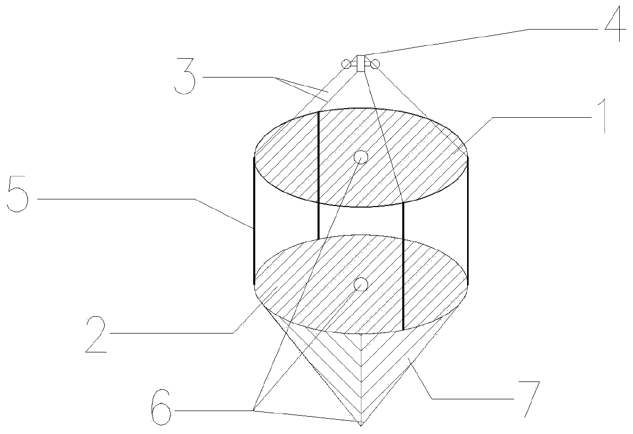
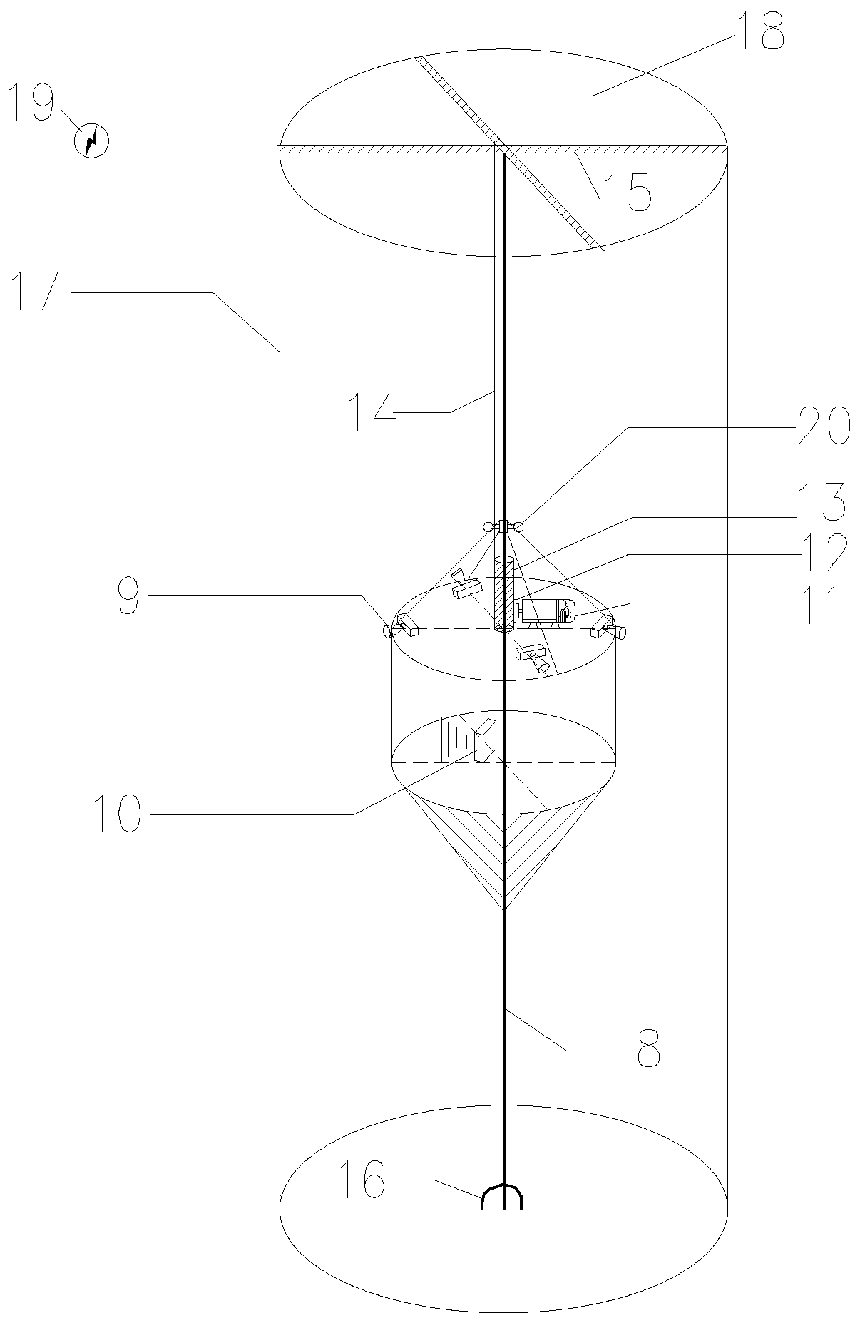
[0037] Such as figure 1 shown and figure 2 As shown, the present invention provides a kind of inspection system of traffic tunnel shaft, including guide rope 8, inspection platform, lifting power device, detection instrument and control processing equipment;
[0038] The guide rope 8 is a metal rope with a rough surface, which is used for guiding and pulling the lifting and lowering of the inspection platform;
[0039] There is a circular hole 6 on the top and bottom of the inspection platform, and the guide rope 8 passes through the two circular holes 6;
[0040] The lifting power device is connected with the inspection platform and installed on the guide rope 8, which is used to fix the inspection platform on the guide rope 8, and is also used to provide lifting and lowering power for the inspection platform;
[0041] The detection instrument is installed on the inspection platform to detect the structural condition of the shaft;
[0042] The control processing equipment...
Embodiment 2
[0056] The inspection platform in Example 1 is equipped with 4 cameras, which correspond to the detection of a certain direction within a range of 90 degrees. Since the well wall is a curved surface, after the image taken by it is transmitted to the industrial computer, the on-site operators can see It is also an image of the shaft wall with a certain radian, and the position of the camera is fixed, so the operator cannot use the image to accurately locate the position of the shaft wall where surface water leakage and block drop occur.
[0057] In order to solve the above-mentioned technical problems, further optimization on the basis of Embodiment 1, the following technical solutions are adopted: the wellhead of the shaft is equipped with a cross-shaped marker, and the image collector 9 is calibrated with the cross-shaped marker through monocular visual recognition. Specifically, in this embodiment, the cross-shaped metal strip installed at the wellhead is used as a marker, an...
Embodiment 3
[0059] Because of the depth of the shaft, the shallow ones are two to three hundred meters, and the deep ones can reach five or six hundred meters. During the actual inspection process, the bottom of the shaft will have wind blowing from the bottom of the shaft to the wellhead. In the case of high wind speed, it will blow the inspection platform hanging on the flat strand steel wire rope, causing the inspection platform to shake from side to side. Affect the detection effect of detection equipment. In order to solve the above-mentioned technical problems, further optimization is carried out on the basis of Embodiment 1, and a windshield 7 is installed under the lower circular plate 2 . The windshield 7 adopts a 1mm thick steel plate to form a conical shape, and is fixedly connected with the lower circular plate 2, such as by welding. The top of the cone of the windshield 7 has a circular hole 6 of 4cm, which is used for the plane strand steel wire rope to penetrate. By using...
PUM
 Abstract
Description
Claims
Application Information
 - R&D
- Intellectual Property
- Life Sciences
- Materials
- Tech Scout
- Unparalleled Data Quality
- Higher Quality Content
- 60% Fewer Hallucinations
Browse by: Latest US Patents, China's latest patents, Technical Efficacy Thesaurus, Application Domain, Technology Topic, Popular Technical Reports.
© 2025 PatSnap. All rights reserved.Legal|Privacy policy|Modern Slavery Act Transparency Statement|Sitemap|About US| Contact US: help@patsnap.com


