Power control circuit board

A power control and power control unit technology, applied in control systems, AC motor control, output power conversion devices, etc. Effect

Inactive Publication Date: 2013-11-20
珠海洛博特科技有限公司
View PDF3 Cites 0 Cited by
  • Summary
  • Abstract
  • Description
  • Claims
  • Application Information

AI Technical Summary

Problems solved by technology

[0002] In DC-AC conversion, the power output stage of motor control generally adopts MOSFET or IGBT bridge topology. The distribution of power units in the power amplifier circuit of the existing power control circuit board is as follows: figure 1 As shown, the three-phase power units A, B and C are arranged in a straight line on the same side of the control circuit board; due to the large current to be controlled, there will be flow in the conductor connecting the power control element (MOSFET or IGBT) and the power supply and load Over a large current, the power consumption and parasitic oscillation introduced by the reactance (including: distributed resistance and distributed inductance) of the power control element (MOSFET or IGBT) connected to the power supply and the load conductor will degrade the performance of the power output stage and make its efficiency Lower temperature, higher temperature, worse working stability, resulting in higher damage rate of power control devices (MOSFET, IGBT, etc.)

Method used


Image

  • Power control circuit board
  • Power control circuit board
  • Power control circuit board

Examples


Embodiment Construction

[0011] Below in conjunction with accompanying drawing and embodiment the present invention is described in detail:

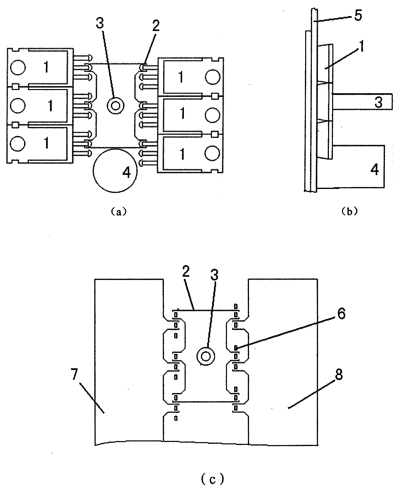
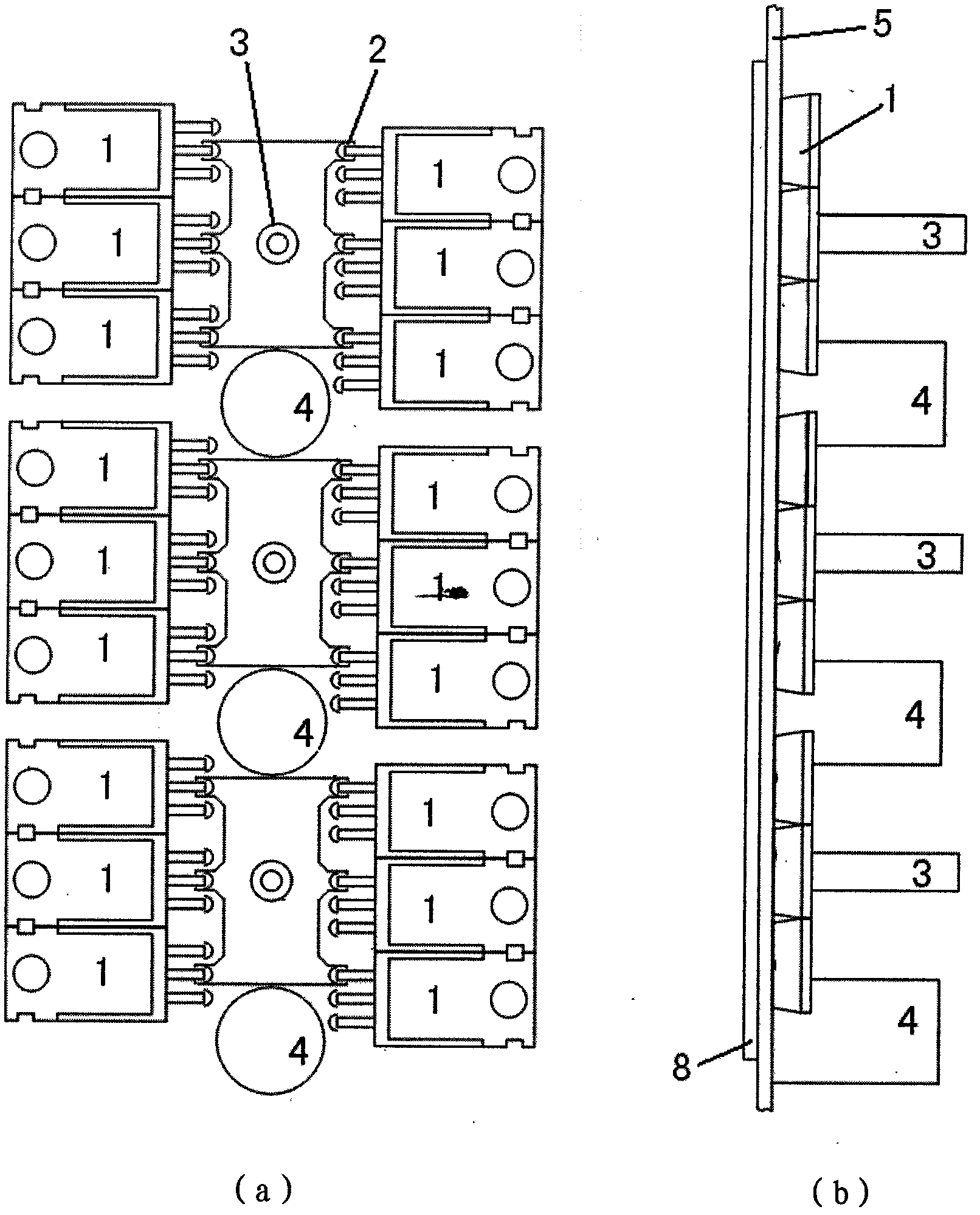
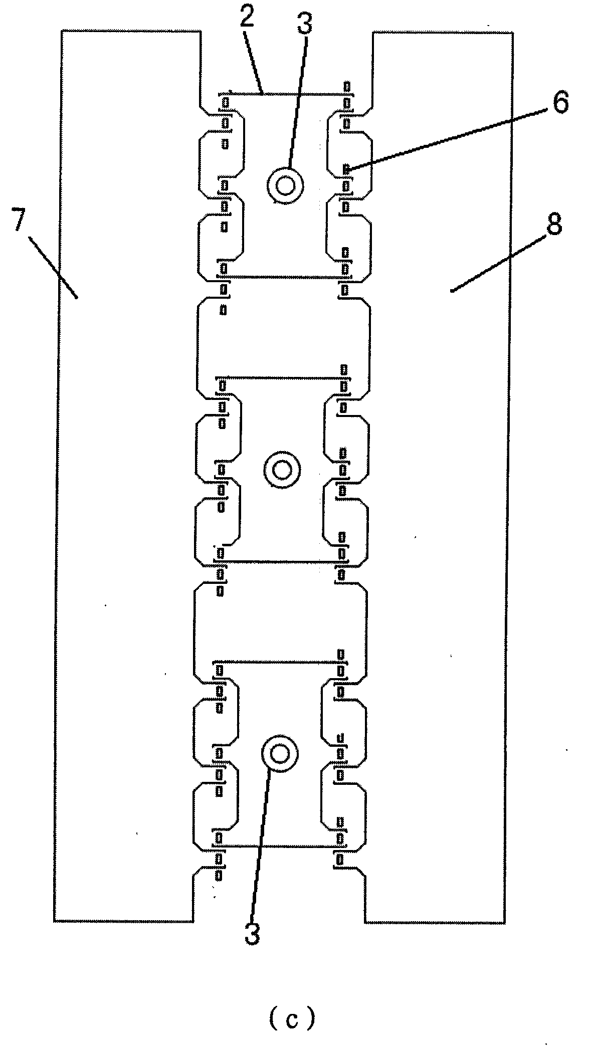
[0012] The power control circuit board of the brushless DC motor in this embodiment includes: a plurality of power control units composed of upper and lower bridge power control devices 1 (MOSFET or IGBT) and filter capacitors 4 . The power control devices 1 of the upper and lower bridges are symmetrically arranged, so that the output terminals of the power control devices 1 are connected with the conductor 2 in the middle of the power control devices of the upper and lower bridges, and the power supply terminals and grounding terminals of the power control devices 1 of the upper and lower bridges The two sides of the upper and lower bridge power control devices 1 are connected nearby, and the filter capacitor 4 is connected between the power supply terminal and the ground terminal of the upper and lower bridge power control devices 1 .

[0013] A plurality of t...


PUM


Abstract

The invention relates to a power control circuit board. Power control devices such as an MOSFET (Metal Oxide Semiconductor Field Effect Transistor), an IGBT (Insulated Gate Bipolar Transistor) and the like of an upper bridge and a lower bridge of the power control circuit board are symmetrically arranged, so that the output terminals of the power control devices are connected in the neighborhood in the middle of the power control devices of the upper bridge and the lower bridge by using conductors; and the power supply terminals and the grounding terminals of the power control devices of the upper bridge and the lower bridge are connected in the neighborhood at the two sides of the power control devices of the upper bridge and the lower bridge, a filter capacitor is connected between the power supply terminals and the grounding terminals of the power control devices of the upper bridge and the lower bridge, and a power control unit is formed. A plurality of power control units are arranged in a shape like a Chinese character 'pin or lu', so that a power control stage is formed, a power positive line, a power ground line and a power output line are connected in the neighborhood, and reactance (distributed resistance and distributed inductance) of the conductors of the circuit board is reduced to the minimum. The performance and the efficiency of the power output stage are increased.

Description

technical field [0001] The invention relates to a power control circuit board, in particular to a power control circuit board for DC-AC conversion or motor control. Background technique [0002] In DC-AC conversion, the power output stage of motor control generally adopts MOSFET or IGBT bridge topology. The distribution of power units in the power amplifier circuit of the existing power control circuit board is as follows: figure 1 As shown, the three-phase power units A, B and C are arranged in a straight line on the same side of the control circuit board; due to the large current to be controlled, there will be flow in the conductor connecting the power control element (MOSFET or IGBT) and the power supply and load Over a large current, the power consumption and parasitic oscillation introduced by the reactance (including: distributed resistance and distributed inductance) of the power control element (MOSFET or IGBT) connected to the power supply and the load conductor wi...

Claims


Application Information

Patent Timeline
Patent Type & Authority Patents(China)
IPC IPC(8): H02M7/521H02P27/06
CPCY02P80/10
Inventor 唐险峰
Owner 珠海洛博特科技有限公司
Why Eureka
Try Eureka