A smelting short net

A short network and main row technology, applied in the field of ore smelting, can solve the problems of large power consumption, power waste, low utilization efficiency of transformers, etc., and achieve the effect of reducing reactance

Active Publication Date: 2022-06-21
三门峡强芯铸造材料有限公司
View PDF0 Cites 0 Cited by
  • Summary
  • Abstract
  • Description
  • Claims
  • Application Information

AI Technical Summary

Problems solved by technology

[0003] Electricity is the main cost in the production process of pearl sand. In the prior art, the three main rows are arranged in parallel on the same plane. Due to the large current passing through the main rows, "enhanced phase" and "weakened phase" are generated between the three main rows. Lead to power transfer; the positions of the three electrode rods are relatively fixed, and the current in the three main rows will change after a period of use. When the current is too high, it will cause waste of electric energy. When the current is too low, the arc heat generated by the three electrode rods Low temperature, not up to the temperature required by the process, short grid structure and unreasonable space layout, often resulting in low power factor, large power consumption, low transformer utilization efficiency, and high production costs

Method used


Image

  • A smelting short net
  • A smelting short net
  • A smelting short net

Examples


Embodiment Construction

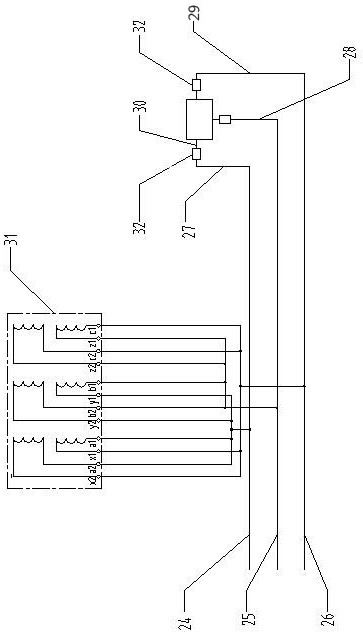
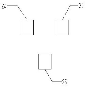
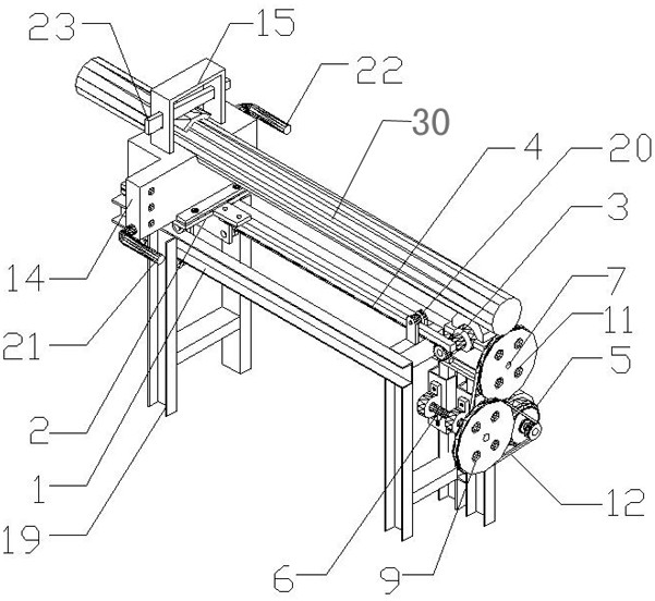
[0023] like Figure 1 to Figure 6 As shown, a short smelting net includes a first main row 24, a second main row 25, a third main row 26, and a corresponding connection with the first main row 24, the second main row 25, and the third main row 26 respectively. The first branch row 27 , the second branch row 28 and the third branch row 29 are provided with electrode rods 30 on the first branch row 27 , the second branch row 28 and the third branch row 29 . The first main row 24 , the second main row 25 and the third main row 26 are arranged parallel to each other, the second main row 25 is located below the first main row 24 and the third main row 26 and the first main row 24, the second main row 25 and the third main row The distances between the rows 26 are equal to each other; the first row 27, the second row 28 and the third row 29 are respectively connected with the electrode rod 30 through the electrode pushing device 32; the electrode pushing device 32 includes a linear ...


PUM


Abstract

A smelting short net, comprising a first main row, a second main row, a third main row and a first branch row, a second branch row correspondingly connected to the first main row, the second main row, and the third main row and the third branch row, the first branch row, the second branch row and the third branch row are all provided with electrode rods, the first main row, the second main row and the third main row are arranged in parallel with each other, and the second main row The row is located below the first main row and the third main row and the distance between the first main row, the second main row and the third main row is equal; the first branch row, the second branch row and the third branch row respectively pass through The electrode pushing device is connected with the electrode rod; the electrode pushing device includes a linear propulsion mechanism and an electrode rod fixing device arranged on the linear propulsion mechanism, the electrode rod fixing device is made of conductive material, and a There is insulation.

Description

technical field [0001] The invention relates to the field of ore smelting, in particular to a smelting short net. Background technique [0002] Pearl sand has been recognized by the foundry industry as a precision casting material, and its usage is gradually increasing. The principle is to connect an electrode rod through three main rows through high-voltage three-phase electricity, and then generate an arc through the electrode rods on the three main rows approaching each other. Heat is released, and the production of orb sand is carried out by the heat generated. [0003] Electricity is the main cost in the production process of pearl sand. In the prior art, three main rows are arranged in parallel on the same plane. Due to the large current passing through the main rows, "enhanced phase" and "weakened phase" are generated between the three main rows. Lead to power transfer; the positions of the three electrode rods are relatively fixed, and the current in the three main ...

Claims


Application Information

Patent Timeline
Patent Type & Authority Patents(China)
IPC IPC(8): H05B7/11
CPCH05B7/11
Inventor 曾小平任龙选
Owner 三门峡强芯铸造材料有限公司
Why Eureka
Try Eureka